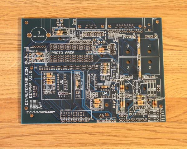
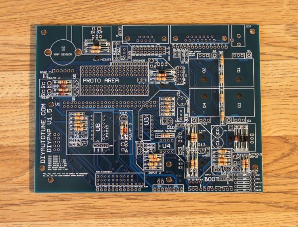
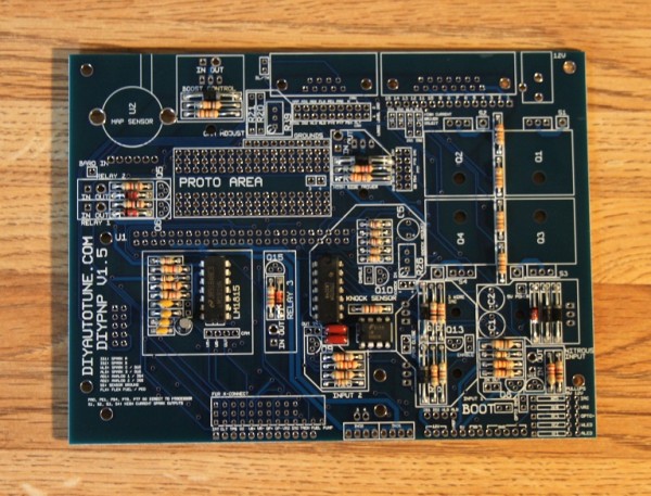
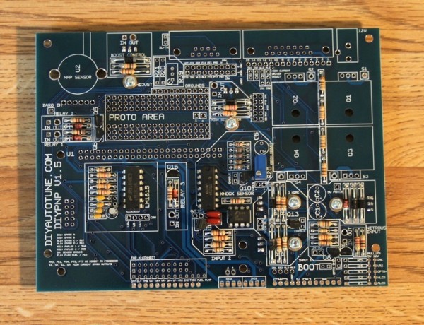
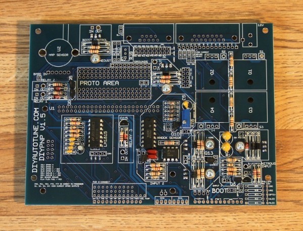
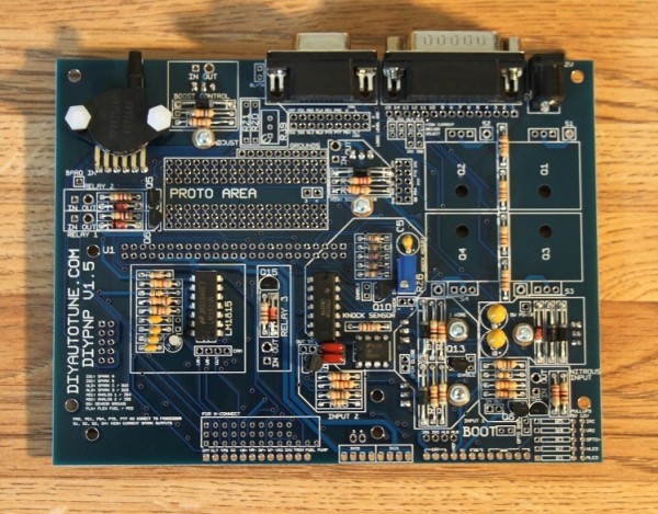
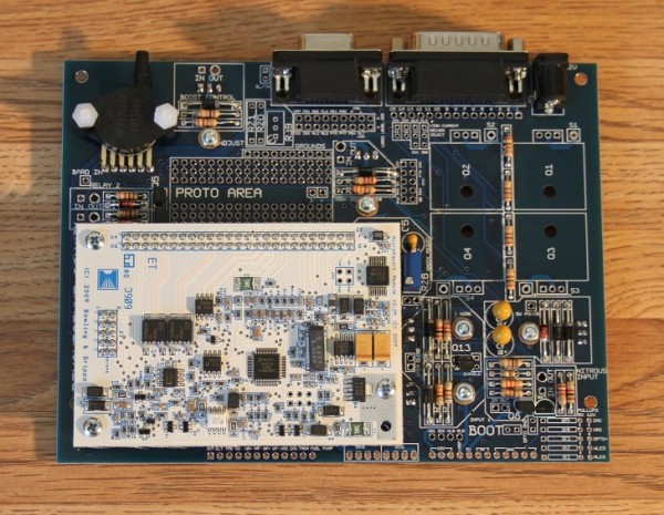
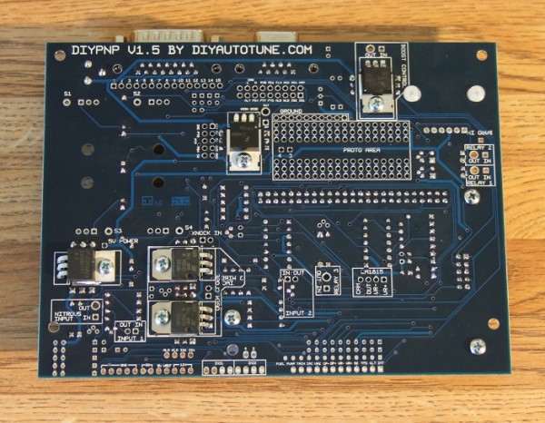
DIYPNP Main Board Assembly
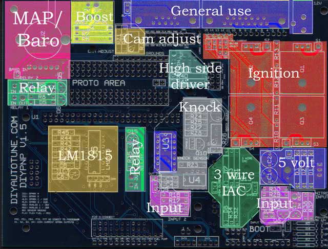
First, you will want to decide which components you will be using, as not all installations need all components. Here is a list of what parts go with what circuit. Note that U3 is used for multiple circuits, and must be installed for any of the circuits to work. There are a couple parts that we’ve included in the kit, marked in green on the component labels, that are for common mods that may not be needed and do not go in one of the usual designated holes. These will be covered in later sections on ignition control and extra outputs.
Note that some boards have extra components on the adapter board that you may want to assemble as well. See these pages for adapter boards with special components.
- N52 and D56: stepper driver
Note that the 3 wire IAC driver is now standard on the v1.5 main board, so it has been omitted from the adapter board.
If you need a bill of materials, you can download it here: DIYPNP V1.5 BOM
All applications:
- U1 MicroSquirt module
- U5 voltage regulator
- D1, D2, D3
- Bootloader, Opto GND, and BL/TH jumpers
- C1 and C2
- DB9, DB15, 12V jack
Internal MAP sensor: U2
Internal Ignition Modules: (optional for most installs)
- Spark A: Q1, R13
- Spark B: Q2, R12
- Spark C: Q3, R11, R1 (100 ohm)
- Spark D: Q4, R10, R2 (100 ohm)
Note that the above spark outputs are only used when high current ignition outputs are needed; that is, when your coil does not have a built in ignition module and your vehicle does not have an external module.
Most applications do not need these, with the main exception being Bosch applications.
The Nipponsenso and JECS kits do not include any of these transistors in order to keep your costs down, while the Bosch 55 pin kit includes one transistor for distributor based spark output.
Extra spark output transistors are sold separately here.
Relay 1: Q5, D6, R8
Relay 2: Q6, D5, R9
Relay 3: Q15, D9, R35
12 volt output: R40, R41, Q17, D11
Input 1: R14, R15, R29, R30, Q8, U3
Input 2: R16, R17, R18, R19, Q9, U3
Nitrous / +12V input: R37, R38, Q14
Knock: C3, C4, C5, Q10, R22, R23, R24, R25, R26, R27, R28, U3, U4
Boost control: D4, R6, R7, Q7
Camshaft position sensor adjustment: R20, R21, R39 (note: It’s very rare you will use all three of these, these are for fine tuning the cam ignition input.)
3 wire IAC driver: R31, R32, R33, R34, Q11, Q12, Q13, D7, D8
LM1815 VR Conditioner: C6, C7, C8, C9, C10, R36, R42, R43, R44, R45, U6
Assembly:
These directions assume you will be using all circuits; feel free to omit any components your build does not need, as listed above. This assembly procedure takes you through a ‘quick assembly’ process.
Generally speaking that means you’ll be installing the shortest components first, then the next tallest, on up to the tallest components on the board.
This way you can install the components, flip the PCB over on a flat surface which will hold all of the components in place while you solder them in. Then install the next taller set of components and repeat until the board is finished.
Note that there are are few components where orientation is important and this is noted below, please take care to properly insert these polarized components marked with a (+/-).
Some of the included components are only used for a few installations. Expect to have a couple parts left over on most builds. So if you have some parts and the instructions didn’t tell you to install them, don’t worry, this is normal so long as you followed all directions.
NOTE: Most components are normally inserted into the top of the board, except when noted as a few transistors do get installed on the underside of the PCB.
The top of the board is the side with all of the components labeled in the silkscreen.
1. Install all resistors in the locations marked on the board except R26 (the knock sensor trim pot), R39 (camshaft signal adjustment), and R1 through R5. Note that R20 and R21 are application specific; do not install anything there unless you have model specific directions for your car saying which ones to use. See the build guide for your specific model on the DIYPNP Available Models page for details.
Note: you will have a couple extra resistors reserved for ‘pull-ups’. These can be used in the R1 through R5 positions or for certain other mods.
2. (+/-) Install all diodes, taking care to match the banded end to the band on the silk screening.
3. If you are using the high current ignition outputs (Q1 through Q4 – only used when you do not have an external ignition module), add the “ENABLE” jumper next to each output you are using.
If you are using the knock sensor, add the “ENABLE” jumper in the knock area.
To jumper these connections, use a short piece of a snipped lead from one of the resistors or capacitors you’ve already installed, bend it into a U shape and solder it in place jumpering the circuit on.
4. (+/-) Install U3, U4, and U6. Taking care to align the notch on the chip with the notch on the PCB’s silkscreen.
5. Install C3, C4, C6, C7, C8, C9 and C10. Note – the C9 and C10 silk screen touches the holes. C9 is in the circle next to C8, while C10 is above C8. C9 is polarized; make sure the + lead is in the hole marked +.
The other capacitors in this step can be installed either way. The gray stripe on C9 is next to its negative lead.
6. Install transistors Q5, Q6, Q8, Q9, Q10, and Q13 through Q15. On transistors with no outline, the flat side goes towards the long side of the triangle.
![]()
7. U5, Q7, Q11, Q12, and Q17 all install on the underside of the board.
Put a dab of heat sink compound on the metalized area of the board and bolt them into place with the provided hardware before soldering them down.
Note that on V1.5B revision boards, you need a mica insulator under Q17 as there’s a small hole in the board that, in rare instances, the transistor can get shorted to if the mica insulator is not installed.
![]()
![]()
8. Install R26. The side where the “wheel” goes is marked on the silk screen. If using R39, install this too.
9. (+/-) Install C1, C2, and C5. Note that all these capacitors are polarized. The + lead goes in the square hole.
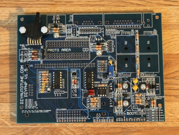
10. Install U2. It mounts on the top side of the PCB, with the vacuum port facing AWAY from where you will be placing the MicroSquirt Module.
The leads are bent 90deg towards the PCB. The notch on the lead indicates pin#1 and should fit into the square hole on the PCB.
If using a MapDaddy, use a bit of jumper wire to connect the baro output pin on the MapDaddy to the small hole marked “BARO IN” on the mainboard.
11. Install the DB9 and DB15 connectors, and the 12 volt power jack.
12. If your kit includes any of the transistors Q1 through Q4, install them using the included heat sinks and heat sink compound.
Note that most ignition outputs do not need Q1 through Q4. On Bosch 55 pin ECUs, Q1 is included and Q2 through Q4 are omitted; Nippondenso and JECS kits do not have Q1 through Q4. These may be added in order to drive coils directly.
13. Install the hex standoffs on the mainboard. To do this put a screw through from the bottom of the mainboard into the hex standoff and tighten until nice and snug. Don’t break the PCB, Brutus.
You want to install these standoffs in the holes that will align with the two top corners of the MicroSquirt module, and in one of the holes at the bottom, the hole closer to the middle of the PCB.
On the mainboard the top two holes are pretty obvious, the bottom hole is the one just under the words ‘Sensor In’.
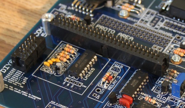
14. Now, for the headers that mate the MicroSquirt Module to the Mainboard. The only trick with these is you must make sure they are flush with the PCB they are soldered into.
If they sit at an angle then they will not mate properly with the opposing pair of headers. The simplest way to ensure this, is this:
- Snap the Male 50 pin (2×25) header and the Female 50 pin (2×25) header together. Do the same with the male/female 10 pin (2×5) headers.
- Insert the female end of these two header assemblies into the mainboard. That would be the side with the now mostly-hidden header (hidden by the male header that surrounds it – the male female reference refers to the metal pins, not the plastic, confusing I know).
- Take another look at how you’ve inserted the headers into the mainboard. Check and see that the ‘keyway’ side of the header, the side with the notch and key, face towards the inside of the MicroSquirt module. Don’t solder anything yet.
- Place the MicroSquirt Module in its new home lining it up with the Hex Standoffs and the Headers you’ve just placed, and slipping the header’s pins thru the module leaving it resting in place. Still unsecured. Still not soldered.
- Insert the remaining three screws into the hex standoffs in and tighten until snug. This will bolt the MicroSquirt to the main board using the hex standoffs and sandwich the headers tightly in between ensuring the don’t move when you solder then and maintain proper alignment.
- Now, solder the 50pin (2×25) and 10pin (2×5) headers into place. From the top of the MicroSquirt Module, and from the bottom of the mainboard.
15. Most adapter boards are pretty straightforward to assemble – just attach the connector with the included screws, and then solder the connector to the main board.
There are exceptions when we’ve included a circuit or two on the adapter board. These adapter boards have their own directions.
Loading firmware
Once you have the board together, you’ll want to load it with firmware. The DIYPNP can be loaded with either Bowling & Grippo code or MS2/Extra, though MS2/Extra will give you access to more of the DIYPNP’s featureset.
The software needed can be found on our Software / Downloads page. You’ll need the boot jumper for loading code. The boot jumper is at the bottom edge of the hood, marked BOOT.
To load MS2/Extra code:
- Place the boot jumper (located to the right of the INPUT 1 label and above the IGN1 – IGN2 – WLED – ALED jumper) across both pins.
- Connect the DIYPNP to your computer using the serial port.
- Power up the DIYPNP. This can be done on a car or you can plug our Stimulator / DIYPNP power supply into the supplied 12 volt port next to the DB15. If loading the code on the car, be sure to unplug the coils and injectors.
- Go into the Program Files/MegaSquirt folder and open the MS2/Extra folder that matches the firmware you wish to load to your DIYPNP. If TunerStudio or other tuning software is running, close it.
- Open the program called “ms2loader” followed by what operating system you have (there are now Windows, Mac, and Linux versions).
- This program will scan your serial port automatically unless you specify a COM port manually. It should report that it has found an MS2 and prompt you with what code version to load. Current production MicroSquirt Modules will prompt you to load MicroSquirt Module code; early production units do not have this feature and you will need to specify that you need the MicroSquirt Module version of the firmware.
- Caution: Loading the MS2/Extra version for a full sized MegaSquirt will cause problems with the ignition output, and may even damage your ignition system. Be sure you load it with the MicroSquirt Module version of the firmware.
- The program will load a new bootloader, at which point you will remove the bootloader jumper, power down the DIYPNP, then power it up again. Once you have pressed a key to continue, the utility will continue to load the MS2/Extra code. It will end with a message stating that verification has succeeded. You can now connect to the DIYPNP with TunerStudio.
To load Bowling & Grippo code:
- Close TunerStudio or any other tuning software you may have running.
- Open the MS2 downloader program.
- Place the boot jumper (located to the right of the INPUT 1 label and above the IGN1 – IGN2 – WLED – ALED jumper) across both pins.
- Power up the DIYPNP. This can be done on a car or you can plug our Stimulator / DIYPNP power supply into the supplied 12 volt port next to the DB15. If loading the code on the car, be sure to unplug the coils and injectors.
- In the MS2 downloader program, go to “file” and then “settings” make sure that it says “com 1″(or whatever com port that you’re using) as the com port and “115200” as the com speed, then make sure that the “Verbosity” is set to 5. Click ok to exit that screen.
- Go back to “file” and then select “open” Go to your “C” drive and find the “program files” folder, open it and find the “MegaSquirt” folder in there. Then find the “MS2-MicroSquirt 2.890″(or which ever firmware that you are looking to use) and select the s19 file, it will have a name like “Monitor_vX.XXX.abs” Double click that and everything should work automatically.
- After that gets done, you’ll power the MS2 off and remove the boot jumper, and set the ECU type in TunerStudio. And that’s it; you have now loaded or reloaded the firmware.
Testing with a Stim?
The DIYPNP does not lend itself well to being tested using a Stim as it does not have a standard connector pinout. If you would like to bench test it in more depth than simply powering it up, one option is to use a JimStim wired to a connector cut out of a junkyard wiring harness. The screw terminals are perfect for attaching a pigtail like this. The V2.2 Stim is not recommended as it cannot test many of the DIYPNP’s inputs and outputs. In particular, its RPM signal will not work with the primary VR input.
Assembly Notes
Here we try to cover some of the other sections of the board where the assembly could vary a bit from install to install based upon the needs of your motor. Each area has its own special notes. These will be covered in more detail on the pages about ignition control and extra inputs and outputs so if this doesn’t clear your mind of all questions right off don’t worry, we cover everything in great detail there.
U3: U3 must be installed if using either the knock sensor or the on/off inputs.
Pull Ups: These can be used for several of the inputs and outputs. Here’s what each of the pullups does.
- R1: Acceleration LED pullup. Used when driving a spark output (either built in or external) from ALED. For the onboard BIP373, use a 100 ohm resistor in the 5 volt position. External modules may require a different resistor though generally the 100 ohm pullup is very commonly acceptable here.
- R2: Warmup LED pullup. Used when driving a spark output (either built in or external) from WLED. For the onboard BIP373, use a 100 ohm resistor in the 5 volt position. External modules may require a different resistor though generally the 100 ohm pullup is very commonly acceptable here.
- R3: Optoisolator pull up. Used with certain Hall effect and optical sensors, usually of the sort called an ‘open collector’. The best value to use here will depend on the sensor. If your application notes don’t specify a value, you may need some trial and error. As a general rule, start with 1K if you’re using a 12 volt sensor or 470 ohms if you’re using a 5 volt sensor.
- R4: VR2 pull up. Use this when the camshaft position sensor is a Hall effect or optical. With most Hall or optical sensors, a 470 ohm resistor in the 5 volt position will work well.
- R5: IAC pullup / flyback diode. If you are using the IAC output as a boost control output, use a 100 ohm resistor in the 5 volt position. If using this as a PWM IAC output ( to control a PWM Idle Valve), put a 1N4001 diode in this slot with the banded end towards in the 12 volt hole.
MAP sensor: The sensor should line up with the outline, with the notched pin in the square hole. Optionally, you can use a MAPDaddy 4 bar sensor, and wire the MAPDaddy barometric pin to the BARO IN hole. This uses the equivalent of the JS5 input (referenced in the tuning software) for barometric correction.
Relays: Each one of these grounds the OUT pin when 5 volts is applied to the IN pin. The IN pin may be connected to PT6, PT7, or PA0. The WLED and ALED jumpers can also drive a relay, but they do not need to be run through the relay circuit and can be connected directly to the relay. Also, some types of ignition modules (Hondas, for example) are better to trigger with relay outputs than the regular ignition outputs. To use these, you can jumper IGN1 or IGN2 to the relay control input. Ignition modules triggered by the relays generally are the sort that are triggered by grounding the input pin to a logic level ground.
Boost: The boost control FET can be driven from PT6, PT7, PA0, or IAC. If using the IAC output, install a 100 ohm resistor on the IAC jumper in the pullup area, and note that the output signal is inverted when using this output. PT6, PT7 and PA0 signals are NOT inverted.
DB9 serial connection: Optionally you can connect the two pins of the BL/TH jumper to send 5 volts to pin 9, which can be used for powering a Bluetooth or other wireless adapter. Some serial devices ground pin 9, so if you are using one of these (like the MegaView for instance), leave the BL/TH jumper out.
DB15 connector: This can allow you to bring out signals that do not fit in the stock harness. The upper row of pins has heavy traces to carry higher current signals, like high current spark and boost control outputs.
High current ignition drivers: These are labeled IGN1 through IGN4. Each of the BIP373 drivers can sink over 10 amps and drive a coil directly, with built in current and thermal limiting. Using IGN3 requires a 100 ohm resistor in the R2 slot on the 5 volt position. IGN4 requires a 100 ohm resistor in the R1 slot in the 5 volt position. The outputs come out on the respective S1 through S4 holes.
Since each transistor has its own heat sink, no mica insulators are needed. Just don’t let the heat sinks touch up against each other or the case. We’ve designed the V1.5 board so it would not be likely for this to happen.
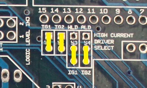
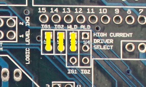
When using the high current ignition drivers, they must be enabled with the jumpers marked High Current Driver Select. These jumpers are marked S1 through S4, for spark outputs 1 through 4 respectively, as per the firing order. To enable the first two high current drivers, jumper the lower holes to IG1 and IG2. The second two may be enabled in sequential or wasted spark fashion. Jumpering the middle holes to WLD and ALD will trigger these from WLD and ALD respectively, allowing for sequential coil on plug on a four cylinder or wasted spark on a six or eight. Jumpering the center holes to IG1 and IG2 will allow “wasted spark COP” output on a four cylinder, letting you use two processor outputs to fire four coils in a wasted spark fashion.
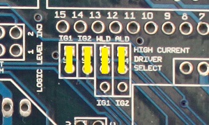
The picture above shows it jumpered for four separate spark outputs. You’d set it up this way for 4cyl sequential ignition, or for 8-cyl wasted spark (using two 4-tower wasted spark coil packs). All outupts, S1, S2, S3, and S4 would be used. These are the outputs to the ignition coils.
Changing the second two jumpers drives all four transistors from the IG1 and IG2 signals for wasted spark COP on a 4cyl. (Wasted spark COP means having an individual coil for each cylinder, but firing them in pairs in a wasted spark manner.) You would still use all four outputs with this configuration, S1, S2, S3, and S4.

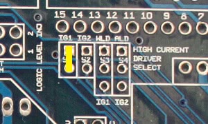
Using only the first two jumpers as in the above image would control a 4cyl wasted spark configuration, such as controlling either one 4 tower coil pack, or two dual tower packs. This setup would use only outputs S1 and S2.
The above configuration would be for either 3cyl sequential or 6cyl wasted spark. Outputs S1, S2, and S3 would be used for this setup.
Using only the first jumper would be the correct configuration for direct control of a single coil used with a distributor. Only output S1 would be used in a single coil setup.
Opto Ground jumper: Connect these two holes together to ground OPTO IN -. If Opto + is jumpered to the main board (as it is on Toyota VAST and Ford TFI ignitions), this jumper should be in place. If OPTO IN + is not jumpered to the main board, leave this out.
Bootloader Jumper: The bootloader jumper is marked BOOT and sits below Input 1. Put the pull off jumper across both terminals to put the ECU in bootloader mode for loading the code. At all other times you can hang the jumper off of a single pin on this header for safekeeping.
Inputs 1 and 2: These are buffered input circuits to protect the processor from miswiring. They supply a 5 volt output that is grounded when you ground the input pin.
Nitrous Input: This is actually a multipurpose 12 volt input. The output of this circuit is 0 volts when a 5 to 12 volt signal is applied to the In pin and 5 volts when the In pin is not connected.
3 Wire IAC: To enable this output, connect the two pins on the Enable jumper, next to Q13. The Open pin connects to the opening pin on the IAC valve and the closing pin connects to the pin that closes the IAC valve.
High Side Driver: This circuit supplies 12 volts, up to 5 amps, to power a relay or solenoid when its IN pin is grounded. You can wire the In terminal directly to FIDLE, WLED, or ALED. You can also drive it by daisy chaining one of the relay OUT pins to the high side driver’s IN pin. Examples of circuits needing the high side driver are Honda VTEC solenoids and GM’s fuel pump relays.
Cam Adjust: This lets you change the trigger voltage on the VR2 input. R20 increases the threshold trigger voltage, R21 decreases the threshold trigger voltage, and R39 can be adjusted to move it either way. If you already have information on what works for your sensors, solder a fixed resistor to either R21 or R20 as documentation recommends. For example, most Nippondenso ignitions work best with a 51K resistor in the R21 slot and R20 empty. If you’re having triggering problems and want to be able to adjust this yourself, leave R20 and R21 empty. Install R39 and adjust as needed to get a clean signal.
LM1815: This can be connected to a VR sensor with the VR+ and VR- holes, and sends a square wave signal on the OUT hole. If you want to feed this output into the VR2 circuit, simply jumper the OUT hole to the CAM hole. The unmarked jumper next to C6 and C7 will ground pin 14 and should be installed in most cases.
Basic Jumpers
Now that we’ve assembled the main board and adapter board, we’ll install the basic jumpers to provide the DIYPNP with power, grounding, sensor inputs, and injector outputs. These jumpers simply run from a pin on the lower edge of the DIYPNP main board to the appropriate holes in the adapter board. First, we recommend you check our available DIYPNP Models page to see if we have a how to guide for your specific car. If we do not, you’ll want to consult a pinout of your stock ECU. You’ll also want to get a copy of the setup spreadsheet from our DIYPNP downloads page, as this can help organize the process.
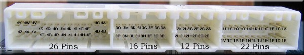
Once you’ve got an ECU pinout, the first step is to figure out how the pin numbering on the DIYPNP matches the pin numbering on your own ECU. On some models, it’s quite simple; the Bosch 55 pin board, for example, always simply numbers its pins 1 through 55, and the numbering scheme does not change from car to car. On the Nippondenso-derived connectors, each manufacturer had their own numbering system, which sometimes changed depending on how many of the connections are used. So you will need to match the factory wiring pin numbering system up to the DIYPNP pin numbering system first. Here is how the pins on the DIYPNP connectors are numbered. Click on the pictures for a closer, clearer view.
N42 pins:
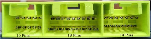
N76 pins:
Once you’ve identified which pins you’ll need for the stock ECU, you’ll need to match them up to the output pins on the DIYPNP. We’ll start by matching up the basic connections for power, sensors, and injectors. We’ll cover RPM input, ignition control, and some of the advanced input and output functions once this is complete. Here are the pins we’re going to focus on for now, and what the pins do. You’ll be able to find them all along the lower edge of the mainboard.
- IAT – Intake air temperature sensor input
- CLT – Coolant temperature sensor input
- TPS SIG – Throttle position sensor signal
- O2 SENSOR – Oxygen sensor input
- FUEL PUMP – Signal to drive a fuel pump relay.
- INJ 1 and INJ 2 – Each of these headers has four connections and can drive four high impedance injectors. All four holes for each injector function the same.
- 12V – Use these connections to supply 12 volt power to the board.
- VREF – 5 volt reference voltage for sensors. Do not tie VREF to the main board 5V points.
- 5V – 5 volt power voltage from the main board voltage regulator. This is meant for powering 5V devices in the proto area. Do not connect this to VREF or analog sensors.
- SG – Signal ground, for sensor returns.
- GND – Power ground.
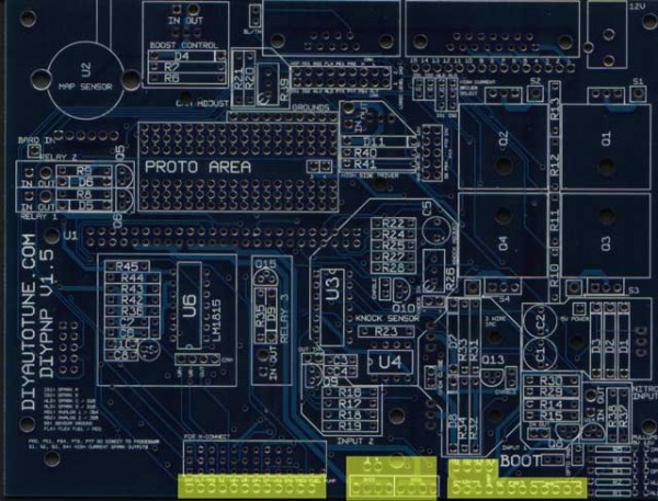
The locations of the jumpers on the main board that you’ll be using in this step are marked in yellow on the picture below. The X-Connect section is for future hardware.
Power and Ground
As you’ve noticed, there are five separate types of power and ground connections on the DIYPNP. Each of them has its own specific purpose. Here is what each connection does.
12V: This connection powers the DIYPNP. Connect it to the pin(s) which get 12 volt power when the ignition key is in the Run and Start positions. We’ve provided you with several 12V pins in case your ECU has more than one. These should not be connected to any pin that receives 12 volt power when the key is off, but only to 12 volt switched power connections.
VREF: This connection provides a 5 volt reference voltage for the throttle position sensor, and can be used for some other types of sensors, such as external MAP sensors. These connections are usually marked with something like “5V,” “VREF,” or “Reference Voltage” in the factory wiring diagram. Caution: Do not let the VREF connection be shorted to ground – this will shut down the DIYPNP. Also, do not tie VREF to the main board 5V power supply (points marked 5V).
5V: The DIYPNP has a second power supply for 5 volt circuits that are isolated from the main reference voltage. Usually you won’t need to connect this to any external wires (it’s more useful for onboard circuits), though if you run across a Hall effect or optical sensor in the external wiring that needs to be supplied 5 volt power, use this jumper. Do not connect to VREF.
SG: Sensor ground. If you have common ground wires coming back from external sensors, connect the pins these wires use to the SG jumper. This is to reduce the amount of noise in signal wires.
GND: Power ground. Connect any ground wires that go to the engine block, battery terminal, or chassis ground to the GND jumpers.
Sensors
The throttle position sensor, temperature sensors, and O2 sensors are fairly straightforward to hook up. The VREF and sensor grounds are covered above; now here’s what to do with the sensor input pins themselves.
IAT: The intake air temperature sensor may be a freestanding sensor, or it may be built into an air flow meter. It generally has two wires, the signal wire and the sensor ground wire. The signal wire goes to IAT and the ground wire goes to SG. Usually the ground wire will merge into another ground wire in the external wiring; in the rare event that you find an IAT sensor where neither wire connects to others or has a clear function, it can be wired up either way.
CLT: The coolant temperature sensor wires up exactly the same way as the IAT sensor.
O2 SENSOR: Narrow band O2 sensors come in one, three, and four wire flavors. With a one wire sensor, simply connect that one wire to the O2 SENSOR jumper. Sensors with more wires will also need the signal ground connected to SG, but they’ll generally work OK without the heater circuit connected. It just takes them longer to warm up. The DIYPNP does not read wideband sensors directly, requiring an external controller. If using one of these, wire the controller’s analog output to the O2 SENSOR jumper.
TPS: The TPS’s signal wire goes here. It is usually marked in the diagram about which is the signal wire. If it isn’t, you’ll need to test the TPS with an ohmmeter. Observe the resistance as the throttle opens and closes. Each pair of pins will behave differently:
The resistance between the VREF and ground pins will remain constant.
The resistance between the ground and signal pins will be low with the throttle closed and high with the throttle wide open.
The resistance between the VREF and signal pins will be high with the throttle closed and low with the throttle wide open.
If your sensor behaves like this, it will be pretty straightforward to connect it to Megasquirt.
If the resistance jumps from infinite (or near infinite) to near zero, you have a switch type throttle position sensor, or possibly a seriously defective potentiometer type TPS. These do not provide very much information that Megasquirt needs, as it can tell if you are at idle or full throttle by the MAP sensor information. You can still use MAP based acceleration enrichment and ground the TPS signal pin through a resistor.
Fuel Control
INJ1 and INJ2: These are your injector outputs. The DIYPNP is batch fire normally, so you will be using two outputs, each of which can drive one low impedance or four high impedance injectors, so each of the four INJ1 holes are the same, and each of the four INJ2 holes are the same. The INJ1 and INJ2 jumpers connect to the injector wires on the adapter board. Usually the best way to pair them is by firing order – connect the first cylinder to fire to INJ1, the second to INJ2, the third to INJ1 again, and so forth. This isn’t a hard and fast rule, and some harnesses will make the injector pairing choice for you. Usually it’ll run fine with pretty much any injector pairing anyway, though some pairings may be a little bit smoother.
Note that there are holes marked 3 and 4 above the INJ2 header. These are wired to the holes marked 3 and 4 in the proto area. These let you jumper a sequential add-on board to the holes in the proto area, making for fewer awkward long runs of wiring.
FUEL PUMP: This pin supplies a ground for the fuel pump relay. Most ECUs will have a ground pin for the fuel pump relay wired straight to the ECU, so you just have to find this wire on the adapter board and connect it to the FUEL PUMP pin on the main board. Some cars, however, have the fuel pump controlled by a switch in the air flow meter. If this is the case, you have two choices on most cars:
- Leave the air flow meter in place and don’t connect the FUEL PUMP jumper to anything. The fuel pump will still operate more or less normally.
- Remove the air flow meter and connect the FUEL PUMP jumper to a wire previously used by the air flow meter. At the air flow meter connector, splice the wire that is now going to the FUEL PUMP jumper to the wire that goes to the fuel pump relay.
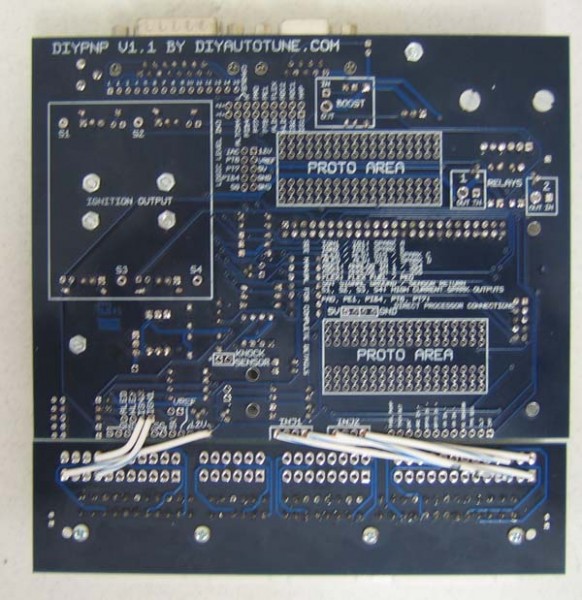
This picture shows a V1.1 DIYPNP partially jumpered (V1.5s jumper up the same way). Note that these jumpers are being put in on the underside of the board – the main board is marked on both sides, although not all adapter boards are.