Article by: Dismonio
Article applies to: All models with an auxiliary fan and resistor.
Electric Fan Resistor Replacement
The electric fan resistor occasionally goes out on the M42/M44 motors as well as the Z3 and some 5-series. In the case of the 1995 318ti, there is only 1 electric puller fan with two speeds located between the radiator and the engine.
When the fan ceases to work, it can be the result of a few modes of failure (as outlined from most common to least common, from my readings).
• Temperature sensor failure (low or high temperature internal switch)
• Resistor failure (cycle fatigue, overheating, water/environmental damage)
• Relay failure (high speed or low speed, high speed relay results in low speed failure as well)
• Fan motor failure (perhaps from a botched job, these fans are rumored to not be rated for 100% duty cycle)
• Fuse failure (investigate as to why)
I feel it’s worthwhile to consolidate some of these failure modes and offer a brief explanation as to how to test and fix some of these problems. They’re spread throughout multiple forums, so let’s add some reinforcement to other’s explanations…
Temperature sensor:
These typically cause problems for one of two reasons- the internal switch fails to activate at temperature or it’s specified for the wrong temperature/resistance values. Check ShiftOEM as to the correct part number, so be sure. The easiest way to test is to check the resistance between the pins.
Fan resistor:
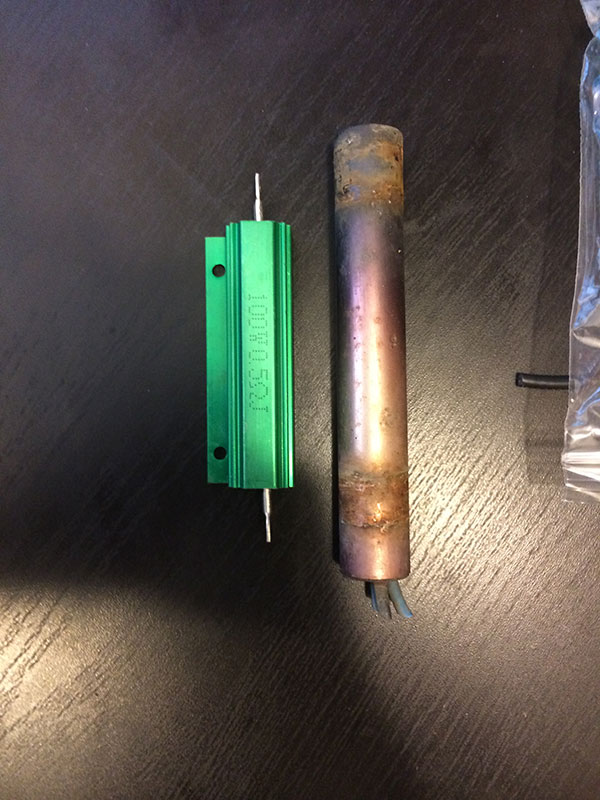
The two speed fan setup works on two voltages. It’s a basic DC motor with two wires, but with two voltage sources. As the only common high current voltage source is the 12VDC system, you can only step down. BMW has designed a fan system that’s designed to operate (at least in this car) without active cooling in temperate climates. When an additional load is applied (such as the A/C compressor) or temperature rises to a sufficient level (the low temp switch on the coolant temperature sensor), the low speed side of the circuit is activated. When this side of the circuit is active, the 12VDC is stepped down through a large resistor on the fan housing (speculated to be 0.5 Ohms, 85 Watts OEM for the 318ti). This allows the fan to run continuously at a lower voltage, while dissipating excess current through the resistor to create the voltage drop. Due to the location and heat cycling of these resistors, they fail over time. The only way to fix this is to replace the resistor or the fan assembly as a whole (salvage or new for ~$300-400).
Relay failure:
The system as mentioned above has two circuits, and the activation of these systems has a common failure point in the relays (particularly the high speed, unloader side). Both of these relays are required to work as they must unload and/or energize their counterpart relay. This is to prevent a short circuit in the system. It’s a relatively simple and effective circuit used all over the place, the relays just sometimes fail. Most commonly the low speed fan side will fail from the high speed relay failing (if memory serves me correctly). These can be tested by probing the fan harness and manually triggering the low and hot coolant temperature sides of the radiator coolant temperature sensor pigtail. Blue and Black referenced to brown should show 12VDC on Blue only (for high speed), 12VDC on Black (for low speed).
Fan motor failure:
This isn’t too common, but I could see either bypassing the resistor or running the fan in high continuously for whatever reason causing these to fail. As I’ve said, I don’t believe they’re rated for 100% duty cycle at 12VDC, and they get ridiculously hot when you run them for any period of time at this voltage.
——————————
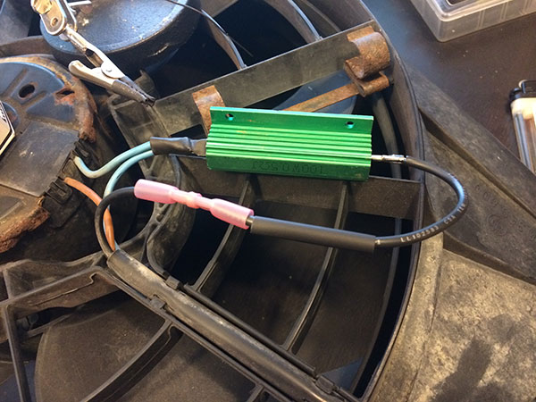
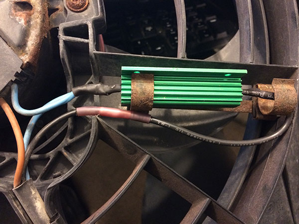
Resistor Replacement:
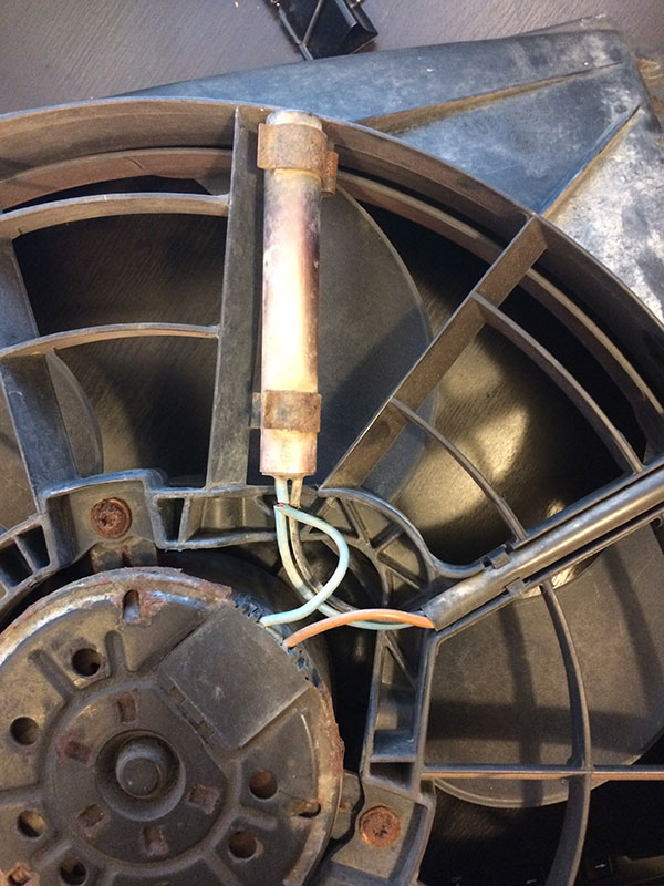
The OEM Bosch resistor is a cigar-tube shaped resistor located on the fan housing. It has 3 wires into it, blue from the harness, blue to the motor, and black from the harness. The brown in the harness is a common ground. Blue to Brown should show some resistance as well as Black to Brown. If Black to Brown shows open, most likely your resistor has failed. If all circuits show open, your fan may have failed.
Amazon has a 0.5 Ohm, 100 Watt resistor available.
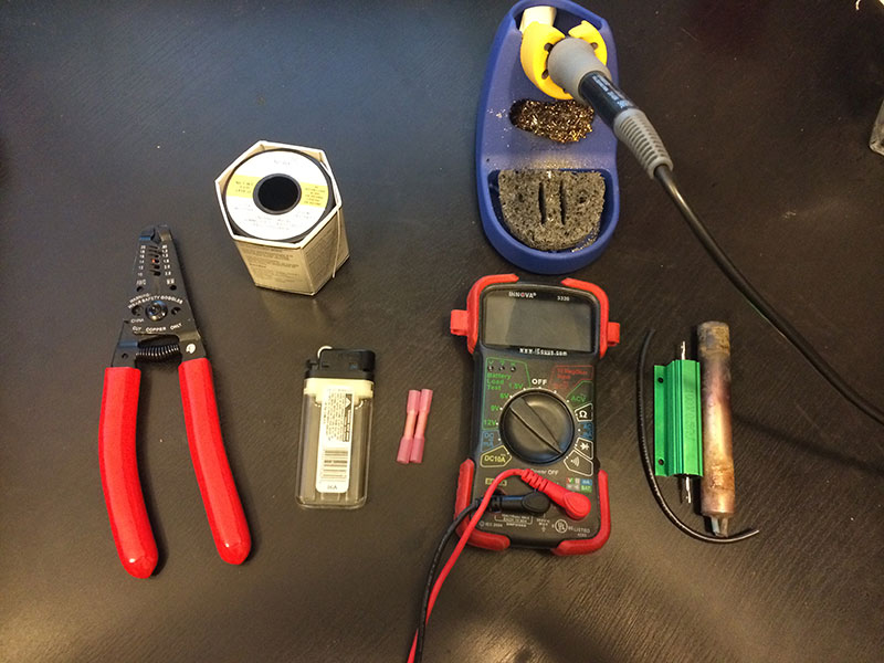
Necessary basic tools – Strippers, solder, solder iron (trusty Hakko FX-888D), harbor freight heat shrink, harbor freight glue butt connectors.
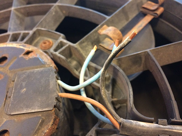
Strip back the wires 3/16in or 5mm. Solder the two blue wires together on one end of the heat sink. Butt connect the black wire to a similarly sized wire, insert your heat shrink. Be mindful of the resistor orientation and solder away. Be mindful of overheating the wires and shrinking the heat shrink prematurely.
Editor’s Note: Test before replacing the bumper / grill cover by turning on the car with the AC turned on.
When the fan turns on you’re good to button everything back up.
~ M.Oswald