Article by: Boris
Article applies to: all BMW e36 models.
A week or two ago the ABS light started coming on. My dad searched around and found out that the Pedal Travel Switch/ Sensor was the problem. He found that the solder broke inside it. The fix is simple and easy.
This is what he wrote:
The pedal travel switch is nothing more then a slide switch. When the break pedal is pressed down, the switch inside the sensor moves to a different resistor. The resistors are in series as the break pedal is pressed down; therefore, resistance increases, but it becomes open when the break pedal is pressed all the way down.
To test the sensor connect a ohm meter at the output of the sensor, and press the break pedal and you should see the resistance start to change according to this chart:

Problem I found on my pedal travel switch is that it was intermittent at the connection point from connection pins to the PCB inside the unit. My ABS light will come on only sometimes, so the failure agreed with what I found.
When troubleshooting the unit make sure you wiggle the connector to see if the resistance reading changes from some resistance to open. If that is the case you have a cold solder joint at the connection pins and the PCB.
To repair the unit, you need an ohm meter, soldering iron, solder, x-acto knife, RTV, and a small screw driver.
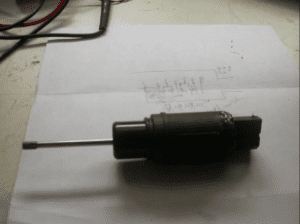
The way to open up the unit is to start from the back where the connector is. Cut through the sealant with a x-acto knife slowly between the body of the unit and the connector pin unit. You might need to hear the save a little to soften up the glue / RTV then use a screwdriver to pry it open.
When I opened my unit the PBC was separated from the connector. If the solder is still holding them together it will be a bit tougher to pull the PCB away from the body. When you get it open pull the PCB and switch out slowly because there is a loaded spring inside.
Inspect all the solder. What I did was clean up all the solder joints to the resisters with solder which and re-soldered them in. Solder the PCB to the connector pins and install the PCB, spring, and connector unto to the housing. Make sure you put them back the way it came out. Apply some RTV to the connector unit and push it back into the housing.


