Article by: CNN
Article applies to: all e39 models.
To see my completed FRONT Suspension Overhaul @ 105K miles, here is the DIY:
About 10K miles later @ 115K miles, the REAR end makes a lot of squeaky noise, especially when getting in and out of the car. The upper control arm ball joint starts to get loose (from torn rubber boot). The car wanders a bit on highway.
- So it is time to do the REAR Suspension Overhaul.
- I decided to leave the Rear Bearing alone for now. If I need to replace the Rear bearing, I’d do that at the same time as the half-shaft boots etc.
- You need to do an alignment after this is done.
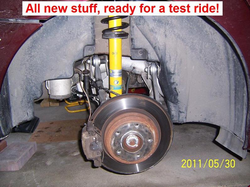
Needless to say, after the REAR suspension is completed and aligned, the car rides on rails, wow!!!
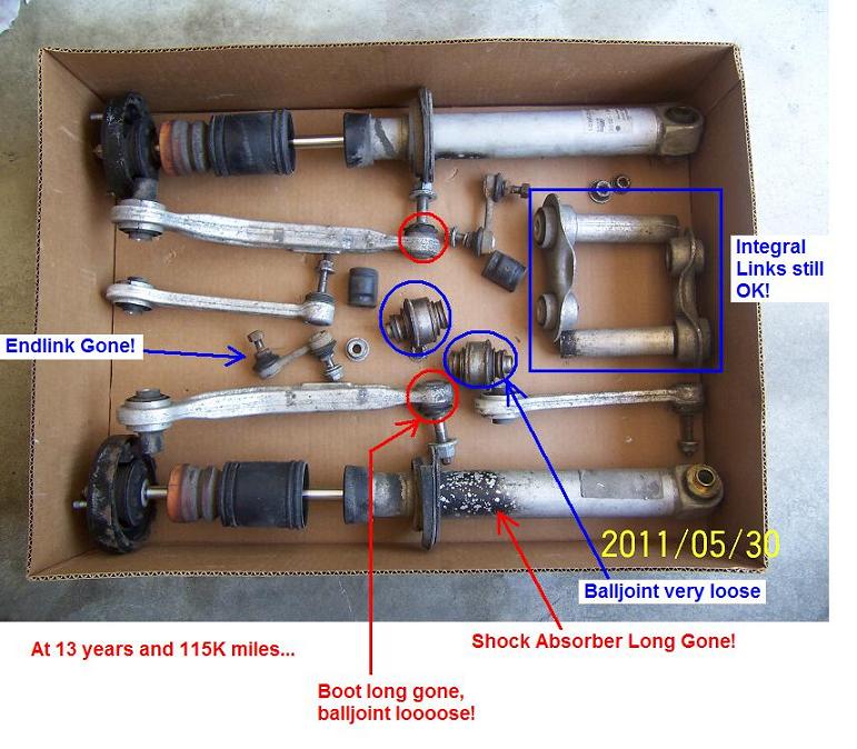
- At 115K miles, here is my observation:
- Rear Ball Joint: long gone
- Upper Rear Control Arm: ball joint long gone
- Upper Front Control Arm: ball joint loose but no play yet
- End links: some play
- OEM Sachs Shock Absorber: long gone!
- Shock Mounts: seemed OK, the rubber portion looked fine.
- Integral Links: seemed OK, the rubber portion looked fine
Some good references:
Rear Wheel Bearing DIY by “mmm635”:
http://www.bimmerfest.com/forums/sho…d.php?t=358553
Bentley’s Youtube Video on Rear Ball Joint Replacement:
http://www.youtube.com/watch?v=MG8jkWMsQw4
The Debate on how to lift Rear End:
http://www.bimmerfest.com/forums/sho…d.php?t=539291
Notes & Special Tools:
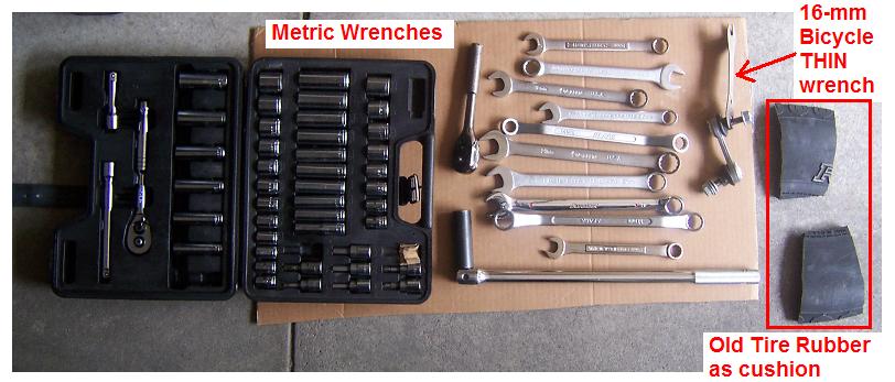
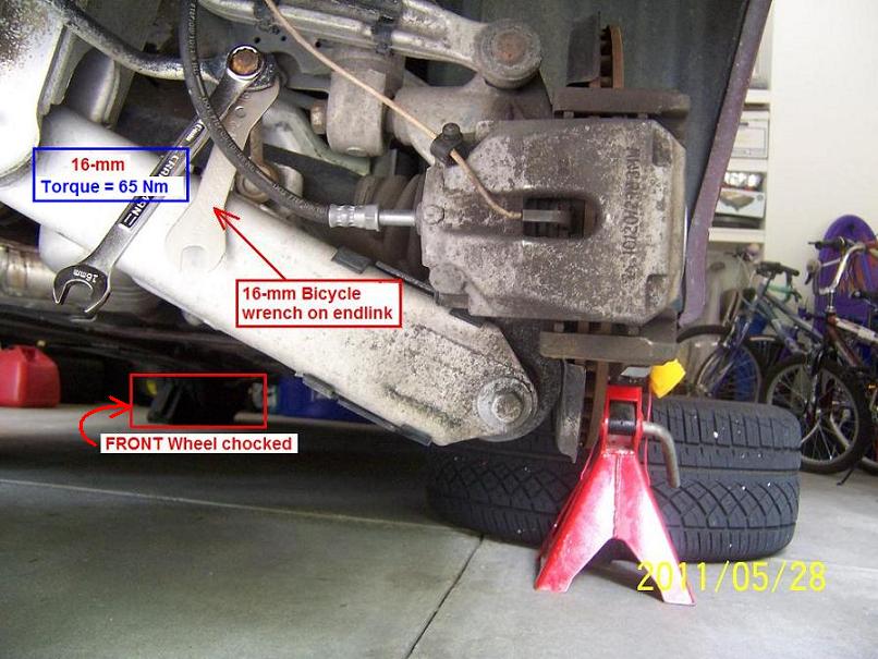
1. A 16-mm thin bicycle wrench is very useful to hold the Sway Bar Endlink bolt while you remove the 16-mm nut.
2. Spray with WD-40 etc. before removing nuts/bolts. The Rear Ball Joint, Spray with a few days beforehand! Just make sure WD-40 does not get into brake pads.
- Place the New Rear Ball Joint in freezer to make installation much easier.
- Undo all nuts and bolts of the parts involved but do NOT remove them yet.
3. Metric Wrenches and Sockets. In particular, you need a pair of 16-mm and a pair of 18-mm wrenches.
4. Rear Ball Joint Nut: 24-mm socket with 1/2″ breaker bar.
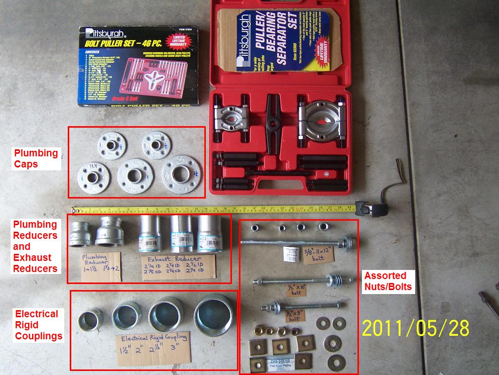
5. Spring Compressors (see picture for type; I bought this from Autozone a long time ago).
6. I rented the Ball Joint Tool Kit from Advance Autoparts for free.
Just deposit $150 + tax. They will refund full amount when you return the Tool Kit.
NOTE: You need to use the Spring Compressor Bolt with the Ball Joint Adapter Tool Kit (read on).
7. Whenever you get anywhere near any rubber, whether it is CV boot, ball joint rubber, etc., pay attention not to damage them.
Once you damage any rubber boot, your beer money is gone LOL.
So please pay extra attention to rubber boots!!!
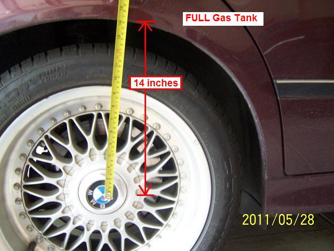
8. FULL gasoline tank so the Rear has the weight needed for pre-loading the bushing.
9. WASH your hand before you touch any trim work!
10. All bolts sizes and torque figures are in the pictures.
11. Work on one side at a time. Leave the other side alone as reference so you can look up the arrangement of the nuts, bolts, washers etc.!
12. Any time I tighten any bolt to spec, I use white-out (liquid paper) to mark the bolt. This way at a glance I know which bolt has been tightened. Alternatively, you can use Sharpie too.
At car factory, they use paint for Quality Control of nuts/bolts as well.
13. Celebrate with red wine and grilled chicken once you are done.
Note: This is my homemade Bearing Adapter Kit used for other jobs but it is no match for the Rear Ball Joint stubbornness LOL!
PROCEDURES:
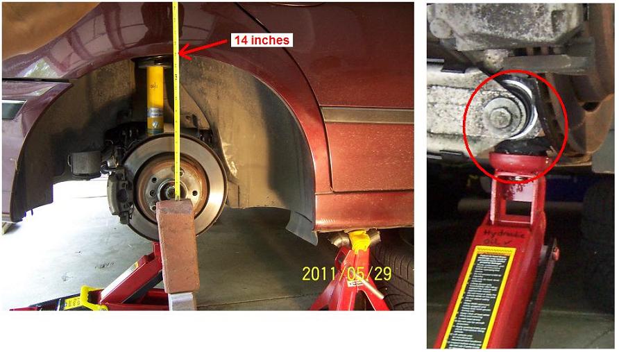
1. With Gas Tank FULL and no significant junk in the trunk, measure fender to wheel hub axis, it was 14 inches for me.
2. Gather your tools etc. Get a box to store trim work fasteners: plastic clips, screws etc. are small and easy to lose them.
3. Open BOTH Rear doors, then hit the center switch to turn lights off.
- Before you get too excited, go wash your hand before touching the trim work!
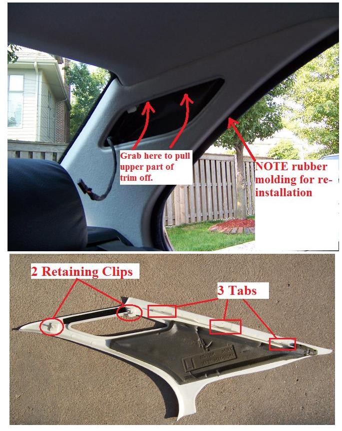
- Pry the TOP of the light off, disconnect wiring (flat screw driver).
- Pull the Trim piece at the TOP and ease it out. Note the locations of the tabs for re-installation.
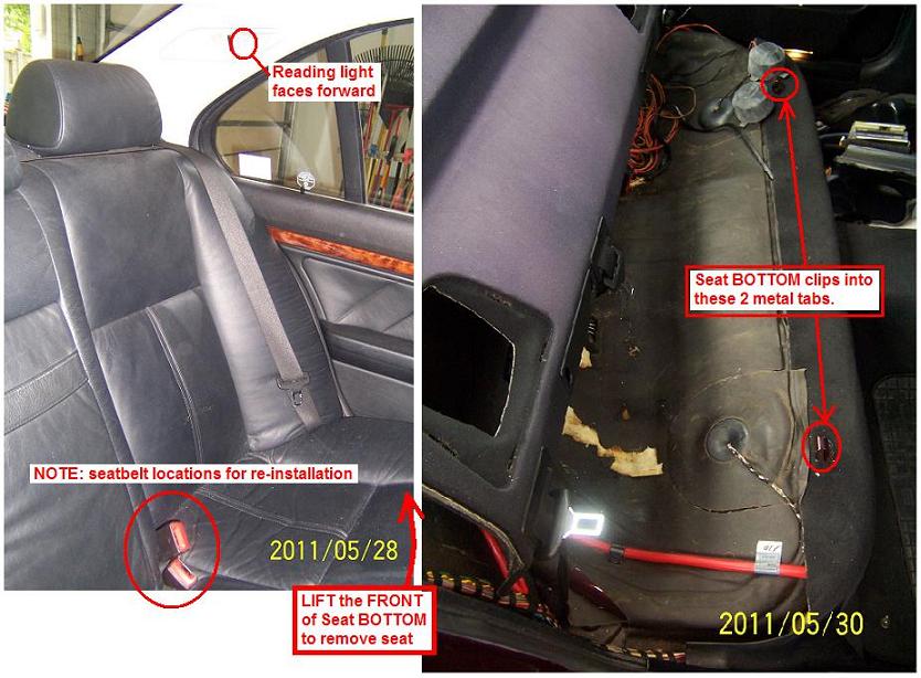
Note: the reading light faces forward!
4. Remove Seat BOTTOM by lifting the Front edge of it then ease it out.
- Note the locations of seat belt buckles for re-installation!
- Also note the locations of the Seat BOTTOM 2 tabs for re-installation.
- Set the Seat BOTTOM in a safe place in your garage.
5. Remove Headrest Cushions by lifting them straight up & set them on the front seats.
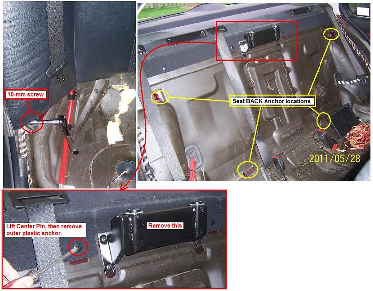
- Remove Seat BACK by removing two (2) 10-mm screws at the bottom, then move the seat belts sideways and lift the Seat BACK straight up. Note the 4 anchor points for re-installation.
- Set the Seat BACK in a safe place in your garage.
- To remove parcel shelf, gently lift the plastic rivet center pin and set it aside.
Remove Center Headrest mounting bracket (Phillips screw driver).
6. Remove speaker covers, then slide parcel shelf forward (no need to remove seat belt).
- Note the rear tabs for re-installation.
- Remove speakers (Phillips screws x 2, and disconnect wiring)
- Use small pieces of wood to lift the insulation to get to shock mounts.
Loosen the 13-mm nuts but do NOT remove them yet.
Before closing rear doors, check the seat belts: you do not want the seat belt buckle to be outside the car when you close the door!

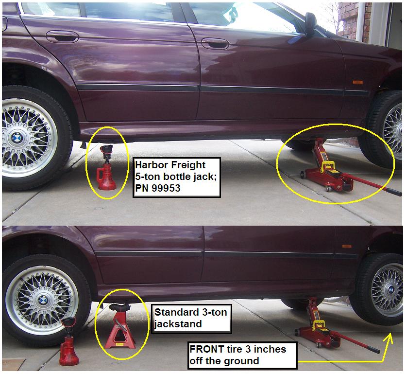
7. Now Raise and Support Rear End.
- Loosen Rear Wheel Lugs.
- Chock FRONT wheels.
- Read the debate on Rear End jacking mentioned above.
If you don’t want to lift via the Rear Differential, then floor jack under FRONT jack pad (Yes Front jack pad), this is enough to lift the REAR jack pads for the lowest setting of my 3-ton jack stands. Good enough for the job.
8. Next, loosen:
- Sway bar bushings: 13-mm.
- End links 16-mm and thin bicycle wrench.
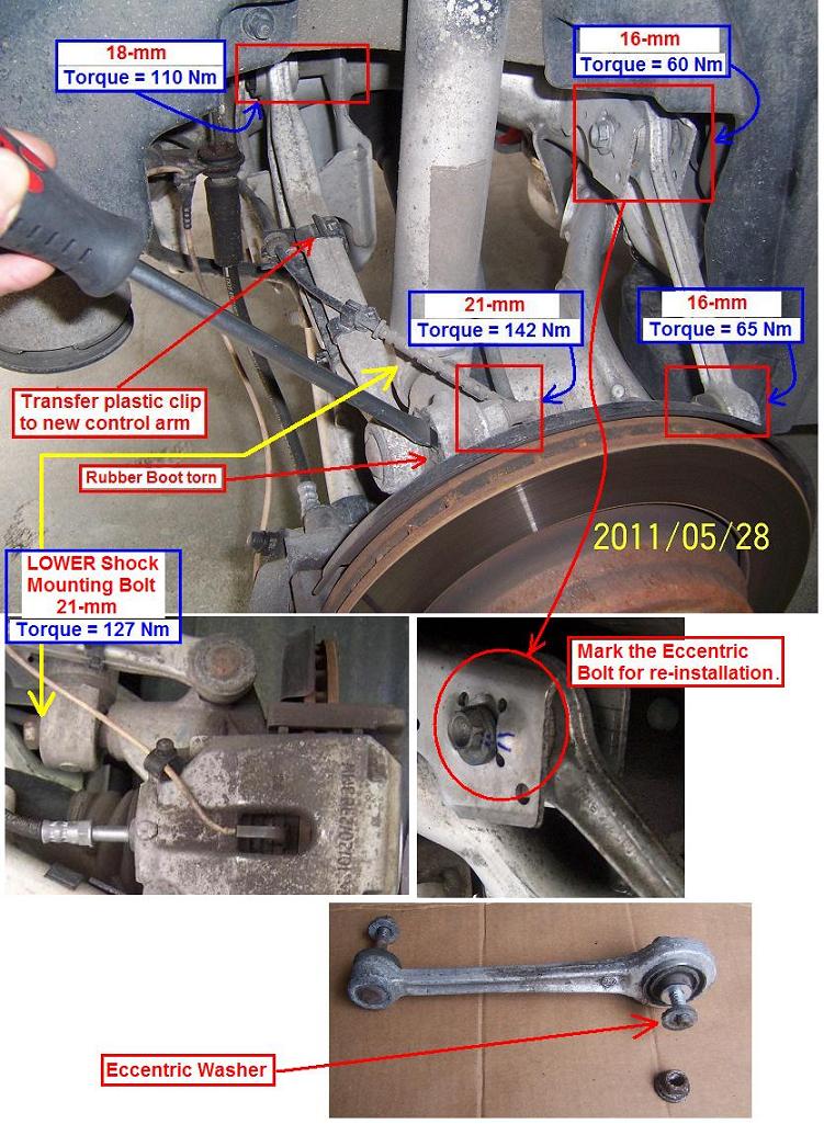
9. Now study this area well!
- Note how the Wheel Speed sensor is routed!
- Note all the bolts and torque values.
- Loosen all of these nuts/bolts but do NOT remove them yet.
- NOTE the FRONT control arm eccentric washer, mark the existing location before removing it.
This eccentric bolt controls toe values.
10. To get the Rear Shock Assembly out of the car:
- Install 3 wheel lugs temporarily so you can step on the rotor to push the wheel carrier down.
- Remove both Front and Rear Control Arms.
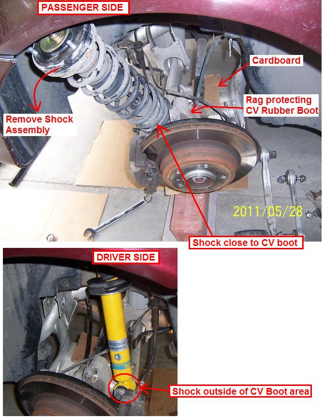
- Place a rag to protect the CV boot.
- Place a piece of cardboard as cushion between the half-shaft axle and the LOWER control arm.
- Remove the 21-mm bolt holding the lower end of the Rear Shock Assembly.
- Now you have two (2) options: either slide the Rear Shock Assembly down in the tight space between the CV boot + control arm (upper part of pic) . . . or . . . slide the Rear Shock Assembly outside of the wheel carrier.
I was lazy and did not unbolt the wheel speed sensor: I simply moved the wiring out of the way. If you are meticulous, then unbolt the speed sensor to make life easier.
11. Once the Rear Shock Assembly is out of the car:
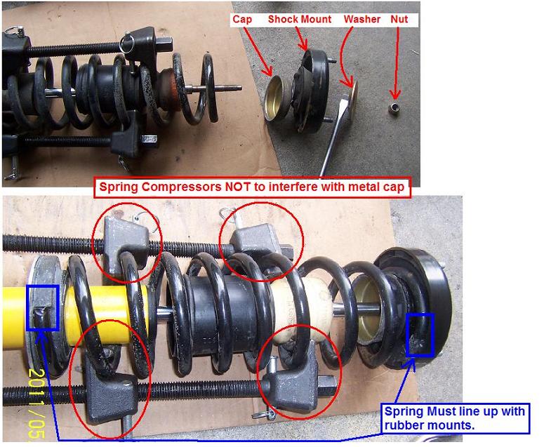
- Observe the setup, compress the Spring as shown.
- Make sure the Spring Compressors do not interfere with the metal cap.
- During install, make sure the ends of the Spring lines up properly with the rubber pads.
- My springs had a small area of surface rust at the LOWER end (near the lower perch), so I cleaned it and flip it upside down (reversed it) so the rusted area is near the TOP at the Shock Mount. Plus, I greased the rusted part for protection. Not sure if this small surface rust has anything significant but what the heck.
- Install the Bilstein HD slide it in the car and attach the shock mount 13-mm nuts loosely.
- Do NOT attach the bottom 21-mm bolt yet!
The lower end of the Shock Assembly will slide in the space between the CV boot and lower control arm. So again, protect the CV Rubber Boot with a rag, or wrap the lower end of the Shock Assembly with a rag and rubber band etc.
12. If you think compressing the Spring and replace the Shock was fun, then wait until you do the Rear Ball Joint: it is even more fun LOL.
- Remove Integral Link.
- Jack the Wheel Carrier up to expose the Rear Ball Joint (recall that you sprayed this way ahead of time with WD-40). If you jack via the rotor, then temporarily install 3 wheel lugs to hold the rotor.
- Review Bentley youtube video above.
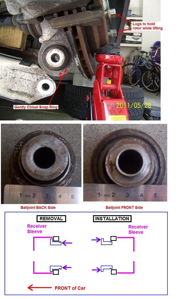
- For the snap ring: gently chisel it out with flat screw driver. It is not as easy as in the youtube video! Mine was bonded to the wheel carrier (itself aluminum, the snap ring is steel!) because they are dissimilar metals.
- To install new snap ring, ease it in with a flat screw driver, taking care not to damage the rubber boot!
- To remove the ball joint, it requires A LOT of muscle power because the ball joint is steel and the wheel carrier is aluminum! So you may need to loosely re-install the control arms to prevent the wheel carrier from moving around while you tighten the tool.
- Study the ball joint: the larger diameter faces the FRONT of the car, so the ball joint is pressed out toward the FRONT. Remove the ball joint rubber boot to make it easier.
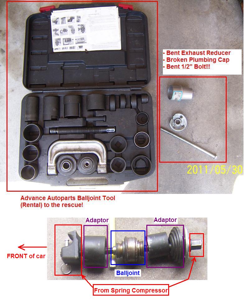
- I used my homemade tool (plumbing cap, exhaust reducers, standard ½” bolt): all bent and broken and the ball joint did not budge. Oh so much fun, if it was not for the J. S Bach Four Orchestral Suites music, I would have spoken French 4-letter word LOL.
- It was late at night, so I gave up. Sprayed more WD-40, went to bed and prayed like crazy.
- Next day I went to church and prayed again, then dropped by Advance Autoparts to rent the Ball Joint Adapter Tool Kit.
- You must use the Spring Compressor BOLT with the Ball Joint Adapter Tool Kit, as only this bolt is strong enough (hardened steel) to remove the ball joint.
- Now install the new ball joint from the freezer. I used some antifreeze (grease) to prevent bonding if I ever need to remove it again!
- Again, watch the ball joint rubber boot and avoid damaging it at all cost. Remember your beer money sits on your being careful LOL.
If you follow my advice and rent the tool (free), your life will be much nicer.
13. Always support the wheel carrier with floor jack.
Now install all new parts, again be careful with any rubber boots. Do not tighten any nuts/bolts until you “pre-load” the wheel carrier.
EXCEPTION: The only 2 nuts that you can tighten right way are the Front and Rear Control Arm’s OUTER ball joints at the wheel carrier because they are ball joints and not polyurethane bushings. Anyway, you can wait until you “pre-load” then tighten them all, it is your choice.
Install:
- Shock Absorber’s lower 21-mm bolt.
- Front and Rear Control arms. NOTE the FRONT control arm eccentric washer, see step #9 above!
- Integral links
- End links
14. “Pre-load” the wheel carrier to weighted position.
- I jacked it up right below the ball joint area as shown.
- In my case it is 14 inches to the hub axis.
- Constantly check because as you tighten the nuts/bolts, this “14-inch” value may change!
- Once the wheel carrier is raised to 14 inches, tighten all nuts and bolts:
- Control Arms’ INNER sides.
- Shock Absorber 21-mm Bolt.
- Integral Link: 18-mm bolt and 24-mm nut.
15. Get ready to lower the car yaaah!
16. Trim work re-installation is basically reverse of removal, however:
- As soon as speakers are installed, turn on radio to check sound. Do NOT forget to re-attach the wiring.
- The Parcel Shelf has rear tabs, make sure it slides in properly.
- When installing Seat BACK, check to be sure it slides in the proper tabs. Do NOT forget the middle seat belt! Make sure all seat belts are properly positioned. Do NOT forget the two (2) 10-mm screws!
- Wash your hands before touching the trim work!
- The courtesy light: reading light faces forward. Again, do NOT forget the wiring connector.
- Check the light operation once done.
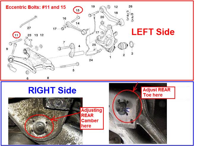
17. Alignment issues:
The book says the LOWER Control Arm Eccentric bolt is used to adjust the “Camber” and the Upper FRONT Control Arm is used to adjust the “Toe”. But geometrically it is a bit more complicated than that. Anyway picture for your info:
Notes:
* The issue of re-using nuts/bolts: All Lemforder parts come with new nuts. I re-used the bolts as all BMW gurus I spoke to say they re-use the bolts.
However, if you are worried then use new bolts.
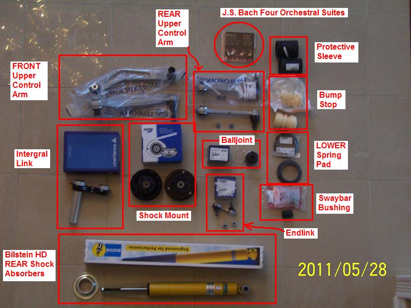
| BMW Part Number | Description | Price | QTY | Sub-Total |
| F4-BE5-2828-H2 | Bilstein HD Rear Shocks | $95.00 | 2 | $190.00 |
| 3352109171 | Sach-Boge Shock Mounts (includes upper spring pad) | $26.00 | 2 | $52.00 |
| 33531091031 | OEM Bump Stops | $13.00 | 2 | $26.00 |
| 31331137932 | BMW Protection Boots | $2.00 | 2 | $4.00 |
| 33531133671 | BMW Lower Spring Pads | $8.00 | 2 | $16.00 |
| 33551093663 | Febi SwayBar Bushings (13-mm) | $3.00 | 2 | $6.00 |
| 33551095532 | Lemforder Swaybar Endlink | $25.00 | 2 | $50.00 |
| 33326767748 | Lemforder REAR balljoint | $41.00 | 2 | $82.00 |
| 33326770749 | Lemforder Integral Links | $37.00 | 2 | $74.00 |
| 33326767831 | Lemforder (L) Rear Upper Control Arm | $114.00 | 1 | $114.00 |
| 33326767832 | Lemforder (R) Rear Upper Control Arm | $114.00 | 1 | $114.00 |
| 33326768791 | Lemforder Guide Links | $94.00 | 2 | $188.00 |
| Total | $916.00 |
– J.S. Bach four orchestral suites Music CD —————— Priceless!