Article by: Paul Axford
Applies to: all models with the vane style air flow meter (this article was written with a 730i).
The AFM is an early-80’s relic from the second generation of electronic fuel injection. This massive sensor sitting dead-center on top of the engine does two things – measure the flow rate and temperature of the incoming air.
The flow rate is determined by measuring the angle of a spring-loaded vane in the path of the air flow, incurring a pressure drop in the process.
There is a potentiometer in the base which translates that angle to a calibrated carbon track potentiometer.
The potentiometer is supplied with a reference voltage such that the wiper (moving contact) produces a variable signal voltage based on the “voltage divider” principle.
The air temperature is measured with a simple temperature-sensitive resistor (RTD.)
As most of us know, the current technology for the measurement of air flow is a MAF (mass air flow) sensor which uses a ‘hot wire’ or ‘thick film’ device which is far less-expensive and does not usually incur a significant pressure drop.
Unfortunately it also does not provide a directly compatible signal with an AFM. To upgrade the system by replacing the AFM with a MAF, an intermediate electrical circuit would be required to correct the mapping of the MAF’s non-linear analog output.
On first glance this would require a microcontroller with analog I/O, not an easy device to throw together unless this sort of thing is your profession.
The pressure drop incurred by the AFM does limit full-throttle engine power. For this naturally-aspirated engine, torque produced is closely proportional to pressure after the throttle.
If the pressure drop is 1 psi (which might be about right) then the unencumbered torque would be (rated torque) x [14.7 / (14.7 – 1)]. That’s 7.3% more – not trivial.
– Troubleshooting –
As primitive the AFM seems, this is a very pricey item so don’t break it!
I checked the operation of the AFM by pushing the vane open while still in the car (measure 0 – 1000 ohms between pins 2 and 4, counting from the nearby rubber mount.)
As the output was not as stable as I would have expected, I removed the AFM and carefully removed the base cover – not an easy task as it’s firmly glued in place with what appears to be silicone rubber.
Be aware, if you remove the screws around the connector you will likely damage the AFM. After removing the cover I cleaned off all the loose sealant from both sides of the joint.
The potentiometer wiper contacts and track clearly needed to be cleaned. I used a small sliver of paper wetted with isopropyl alcohol, slid under the wiper, worked back and forth like sand paper.
I then cleaned the track with alcohol-wetted tissue paper. I didn’t see any point in tampering with the wiper spring force or mess with the calibration, as other people have done.
Next, I shifted the track base very slightly by prying at the edges with a screwdriver. The idea was to move the wiper tracking path to a fresh area.
If I could have gotten the three screws loose I might have considered drilling out the holes slightly to gain a bit more movement. Even after 140,000 km of operation the track was not badly worn.
A quick test with the ohm meter showed that the output was now much more stable.
As the potentiometer housing appears to be completely sealed it clearly needs to contain a dry air environment otherwise moisture will condense out and corrode the electrical parts.
I procured (begged) a small bag of silica gel from a local camera shop, dried it in the oven (150° C / 300° F for 30 min) and jammed it in the hole indicated in the photo below before re-installing the cover with fresh silicone adhesive*.
*I have recently been advised that you must use a “sensor safe” version of RTV sealant which has a very low volatility of acidic gases.
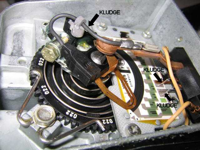
As a side note, my AFM had evidence of design revisions, as clearly the intent of the original designer did not work. (He must be related to the cylinder head guy.)
On the second photo, note the three wire jumpers that provide parallel conductivity to the spring loaded contacts from the connector base to the potentiometer wiper and track.
Clearly the contacts in the original design did not work well after a bit of corrosion took place. This is why including the silica gel desiccant is so important.