Article by: Eric Crawshaw
Article applies to: all BMWs with a Getrag 260/6 manual (5-speed) transmission
Part 3: Reassembly
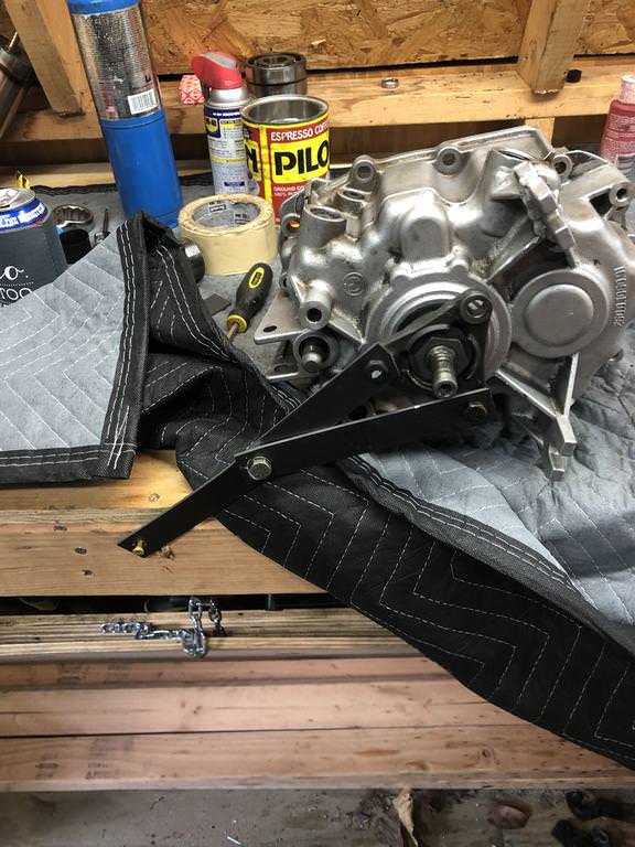
How to reassemble the Getrag 260 in “a few” easy steps!
Well it’s done. It’s back together. It was definitely a bit scary at first, but I was able to get it done. On a scale from 1-10, with 10 being an engine rebuild, this is at least a 10.2 (I have built 2x M20’s). There are just so many small parts and it can be a challenge holding everything in place while trying to assemble it.
Things you’ll need
- Heat gun
- Curil K2
- Oven mitts, leather gloves, or something to handle hot metal
- Thick grease
- Loctite
- Plasti-gauge
- Input Shaft seal
- Output shaft seal
- Selector shaft seal
- Input and output shaft bearings if you want to replace themDrive the input shaft bearing out of the front case. I used a wooden dowel to get down into the case
1. If you want to replace the output shaft bearing, now is the time to do it. Take off the 10mm bolts from the rear of the case and drive the bearing out from the rear of the case. Use the heat gun to heat the case around where the bearing will go and the new bearing should drop in if you’ve heated the case enough. Reinstall all your bolts.
2. During disassembly I forgot to mention that you need to punch out the middle shift rod end plug. Use an extension to punch it out from the inside, it comes out easily
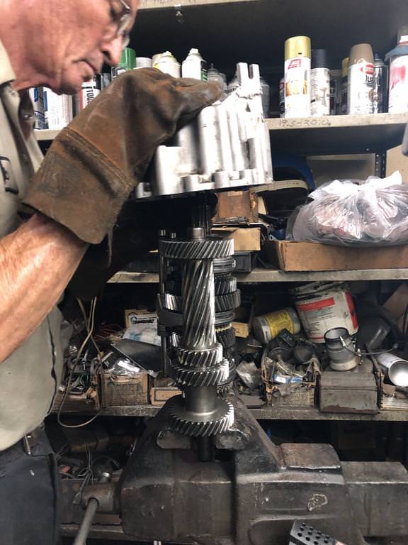
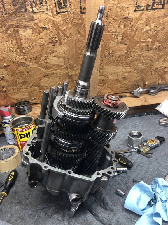
3. Put the gear train into something that will hold it in place, I used a loosely tightened vise. It may help to zip tie the layshaft to the main gear train. Engage 2nd gear and reverse gear.
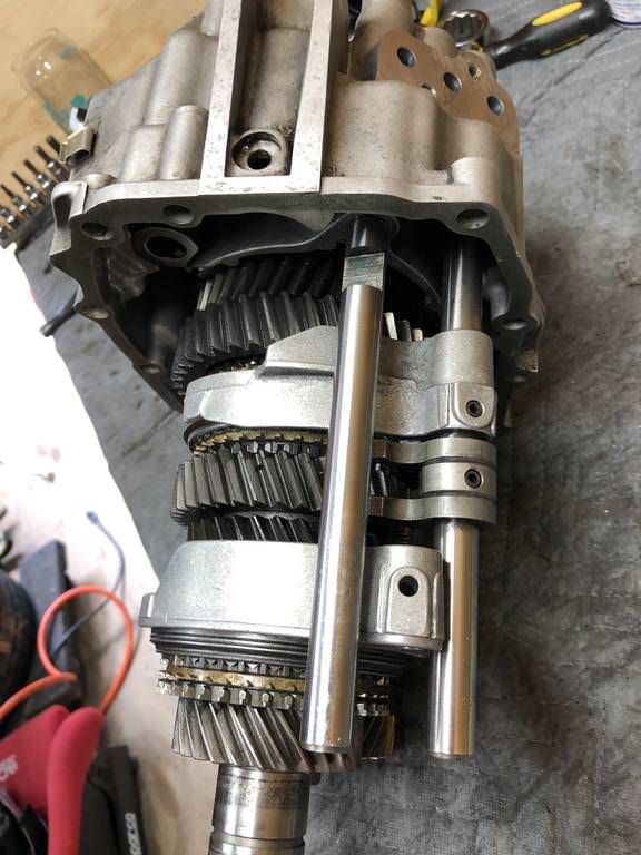
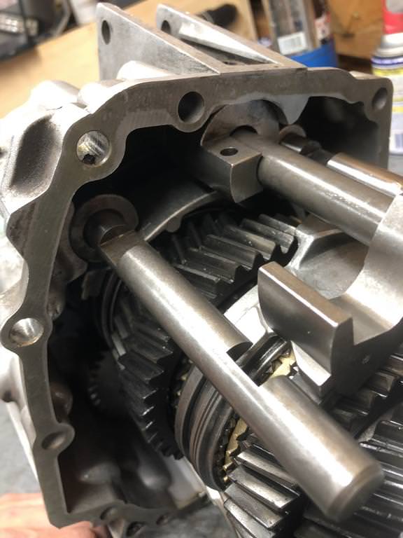
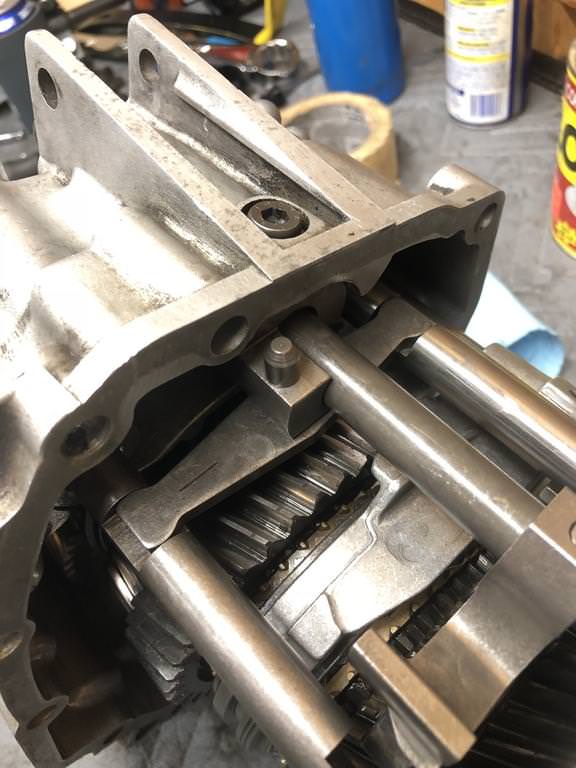
4. Make sure you’re shift rods are lined up to go into the outer two shift rod holes in the rear case. They should slide in easily, don’t force them.
5. Use your heat gun to heat the inner race of the bearing to ~176f. Not having a thermometer I used the “spit test”. Without burning yourself, get some spit on your finger and tap the heated bearing race. If it boils immediately and makes a “hiss”, you’ve got it hot enough
6. Take the case with the heated bearing and push it onto the gear train. If it’s aligned properly, it should go on relatively easily
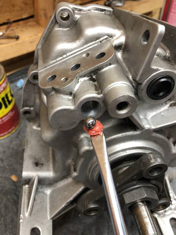
7. Put some grease on a flat head screwdriver and use it to position 2 detent balls in the middle shift rod hole. One goes to the left and one goes to the right.
8. Put the shift rods and forks in their neutral positions.
9. Apply some grease to the 3rd gear shift rod which will fit into the middle shift rod hole in the rear of the case.
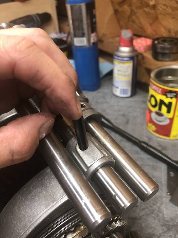
10. Install the pin that goes through the end of the shift rod.
11. Push the 3rd gear shift rod through the shift fork and fully seat it in the back of the case.
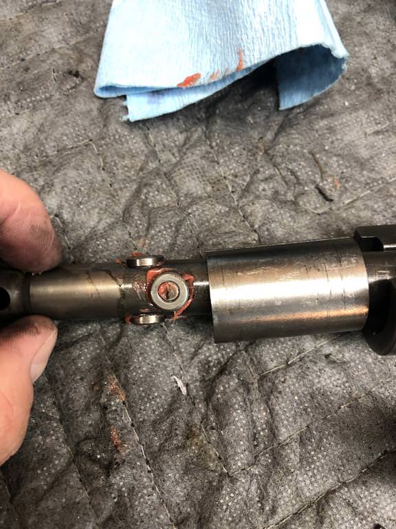
12. While supporting the 3rd gear shift rod, drive in a rolled pin to mate the rod to the fork.
13. Reinstall the rear cover.

14. Insert the 3 detent balls into the rear of the case.
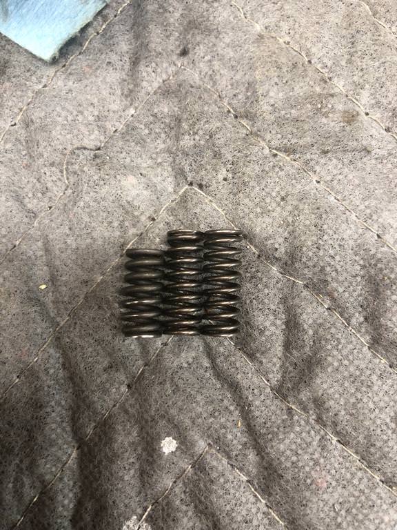
15. Insert the springs above the detent balls. Note that there is potentially a shorter spring. The short spring goes closest to the selector shaft.
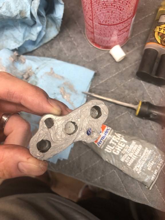
16. Put some RTV on the detent ball cover and torque it down to 10nm

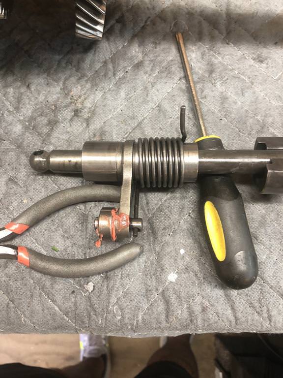
17. If you are like me, you made the mistake of removing the reverse gear spring by taking off the allen bolt from the top of the rear case, you’ll need to reinstall those parts and spring. The trick to fully seating them in the back of the case is to use the selector shaft to rotate the sleeve clockwise while applying pressure towards the back of the case. This will allow you to reinstall the allen bolt
18. Grab your selector shaft, remove the rolled pin if it’s sticking out of the bottom of the operating lever so you can reinstall it from the top
19. Using grease to hold them in place, install the 4 roller bearings on the selector shaft
20. Insert the selector shaft into the rear of the case, making sure the “serrated” end of the shaft with the cuts on it faces what would be the passenger side of the vehicle or else you’ll be coming back to this step
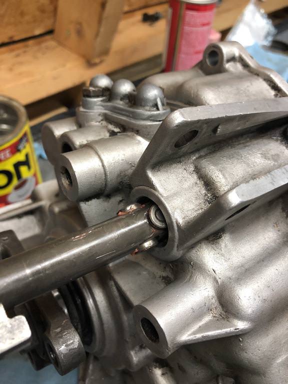
21. While inserting the selector shaft, slide it through the operating lever
22. Insert the rolled pin through the operating lever and selector shaft
23. Lubricate the selector shaft seal and install with an appropriately sized socket
24. Insert the shift operating lever and shift operating shaft. Make sure the groove on the top of the shift operating lever is facing the shift operating shaft
25. Install the locking pin.
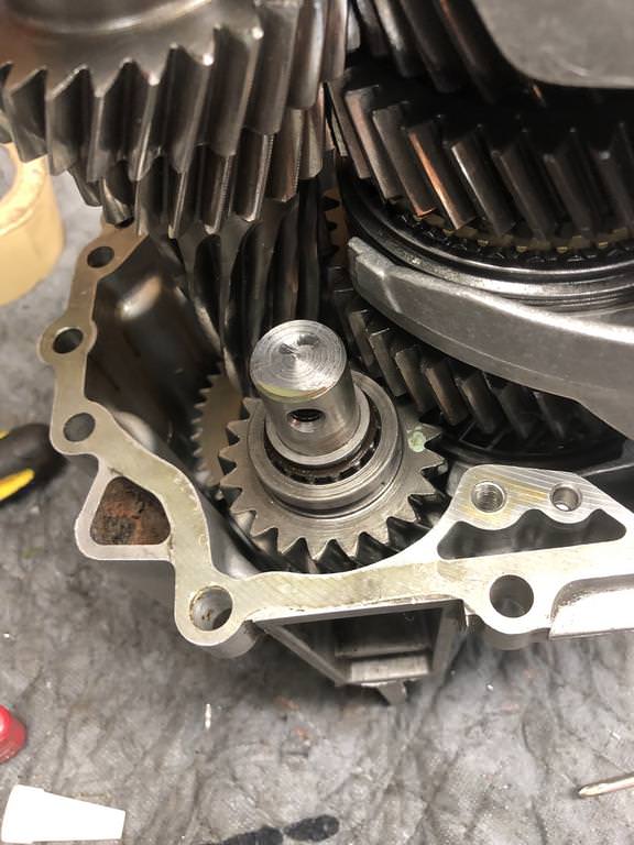
26. Clean the reverse gear shaft sealing surface
27. Paint the sealing surface with Curil K2
28. Install the reverse gear. Use Loctite and torque the bolt to 18ft/lbs
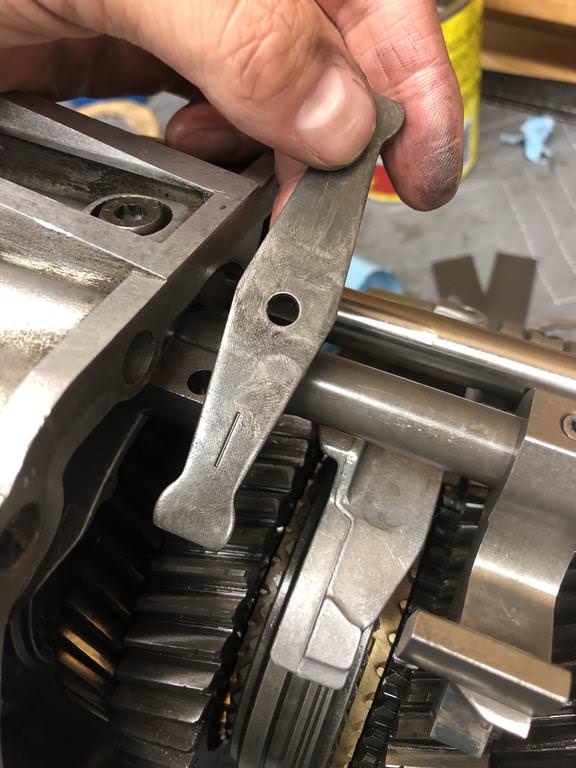
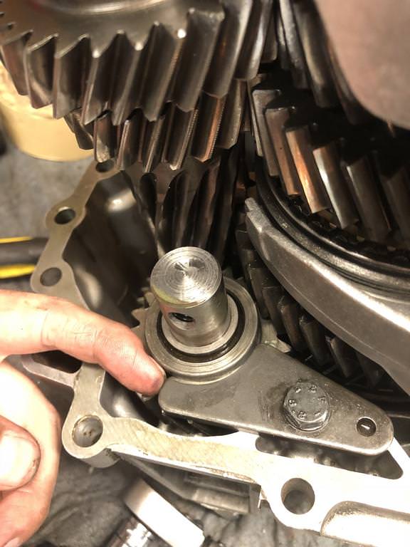
29. Install the reverse gear retaining bracket. Apply outward pressure and torque the bolt to 18 ft/lbs.
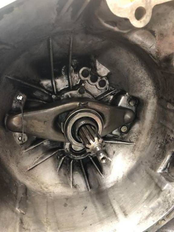
30. Install the output flange onto the output shaft. Install your flange holder, I had to bolt mine to the table to hold it still.
31. Torque the flange nut to 123 ft/lbs to ensure it’s fully seated. Remove the nut, and retorque it to 87 ft/lbs.
32. Install the lock plate over the flange nut and bend the tabs into the grooves.
33. Use some grease to install the layshaft roller bearing onto the layshaft. The side with the plastic face goes on facing the layshaft.

34. Clean the reverse gearing sealing surface on the front case. Paint with Curil K2.
35. Clean the front and rear case sealing surfaces and paint with Curil K2.
36. Place the rear case and gear train assembly onto the ground.
37. Position the front of the case on top and carefully slide it down over the gear train, shift rods, and layshaft.
38. You’ll likely need to jiggle the front case around in order to align everything. Don’t force it, you’ll know when it’s seated properly.
39. The front case should sit down enough onto the guide pin on the rear case, then you can use a hammer to tap the cases together.
40. Install the bolts into the rear of the case and torque to 18 ft/lbs.
41. Use Loctite to install the reverse gear bolt, torque to 18 ft/lbs.
42. Install the guide pin on the top of the case.
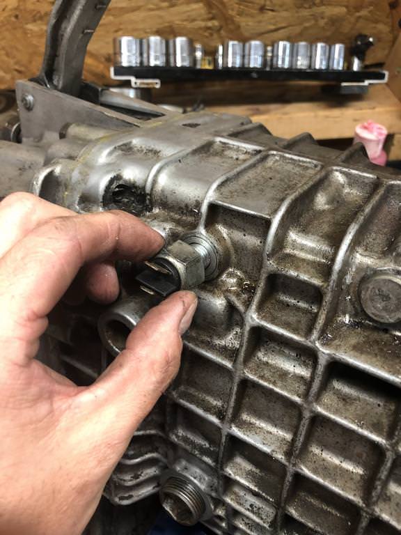
43. Install the reverse gear switch.
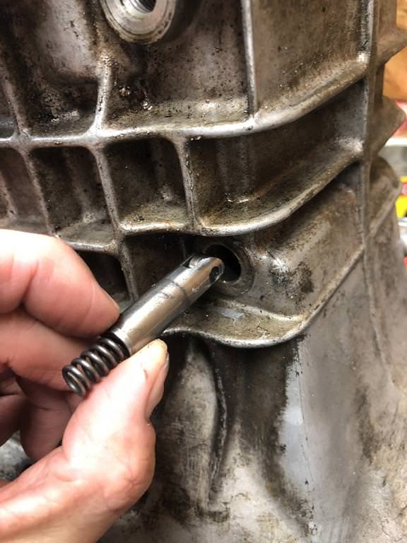
44. Install the selector shaft lock pin and spring into the side of the transmission, hammer in the plug.
45. Heat the input shaft bearing area of the front case. Simultaneously heat the inner race of the bearing to 176f (or use the spit test).
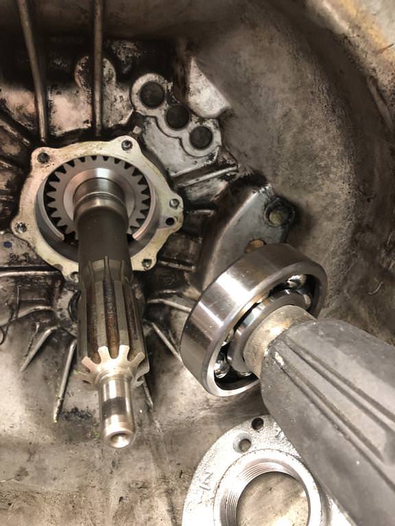
46. Drive the input shaft bearing onto the shaft until it’s fully seated, make sure the side with the visible ball bearings is facing outward (towards the engine).
47. Install the spacer onto the input shaft.
48. Install the new circlip onto the input shaft, if it doesn’t go on, you might need to hammer the bearing into the case a bit more.
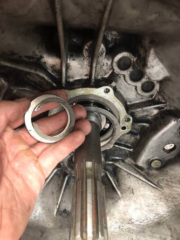
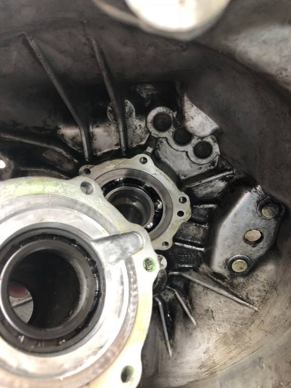
49. You need to check the clearance between the bearing and the guide sleeve, this is where you can use your plasti-gauge. Place a small section on the outer bearing race and install the guide. If the range is not 0-.09mm you need to get a larger shim.
50. Remove the guide sleeve, install the shim, lube the input shaft seal and paint the sealing surface with Curil k2 and reinstall the guide sleeve, make sure to orient the oiling cutout over the appropriate hole (the one that’s not a screw hole)
51. Install the clutch release lever and bearing using grease on all contact points.