Article by: Author unknown
Article applies to: all BMWs.
I decided now would be the perfect time for everyone to learn how to properly read a Turbo Compressor map, and how to choose a proper turbo for your vehicle.
Here we will show a compressor map for reference:
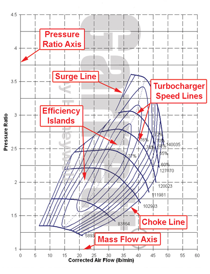
First off on the Y axis is the pressure ratio. This is atmospheric pressure, or 14.7 psi = 1.
The X axis is the air flow in pounds of air per minute or lbs/min .
To convert lbs/min into CFM you factor in the ambient air temp.
Compressor maps use 27 degrees centigrade, or 300 kelvin (To calculate Kelvin, take Celsius and add 273) One cubic foot of air at 300k weighs 0.07282 pounds.
So, at 300k, convert pounds per minute to CFM by multiplying by 13.73.
OK, now you decide how much boost you want to run. Take that amount of PSI, add it to 14.7 (atmospheric pressure) and divide by 14.7.
Lets say you want to run 15 PSI:
Pressure Ratio = (15 + 14.7) / 14.7 = 2.02
Find 2.02 on the Y Axis. Draw a line straight across at this point.. Look at the range on the X Axis the line is passing through the turbo’s efficiency range. In this example the range is from 15 lbs/min to 35lbs/min.
Now, you will need to find the displacement in cubic inches of your engine. You may know this in Liters or CCs, but CI is what we need for this exercise.
Now, VE is volumetric efficiency, this is just the measure for how much air your engine can ingest.
For this write up I’m going to make up an engine for the sake of easier math. Most forums will be able to give you an estimated VE at 6000 RPMs, or the FSM. Believe it or not the math is too involved for even this write up.
So the made up engine is 2226CC or 136 cu in and at 6000 rpm and 90 percent VE ( .90):
CFM = Displacement in CI / 3456 * RPM * VE
6000 * 136 / 3456 * .9 = 212.5 CFM
OK, so this looks pretty good comparing to our graph and early equation. BUT, this is just the amount of air the car will flow N/A.
So if you do this math for a different engine and it doesn’t land in that range don’t concern yourself.
To determine what it will do under boost, you have to determine what density ratio of the compressor and inter-cooling system will give you.
To do that we need to take our boost point and determine how hot the compressor is going to make the air at that pressure level.
Temp(in F) = (((Tin (in F) + 460) * (Pressure Ratio0.283)) – 460)
For 15psi of boost at sea level at an ambient temp of 85F (85F = 300k or 27c)
Temp = (85 + 460) * 2.020^.283 – 460 = 205F
This assumes 100% efficiency. The compressor map tell us how efficient the compressor is going to be at a given pressure ratio and flow level. Since most of the map is at least 70% (.70) efficient or better (adjust this number for what range you’re shooting for).
Our true output temp is:
TrueT = T ideal / efficiency
For our example, 205F – 85F or 120F:
Actual = 120F / 0.70 = 171F
171F is how much the compressor is going to heat the air above the inlet temp. True outlet temp 256F.
Now, what happens at the IC? Pressure Drop, the Temp Drop. Lets assume a 65% efficiency from a small side-mount which isn’t the greatest, but let’s face it, it is reality in a lot of people’s situations (cough stink-fist cough).
To figure out the inter-cooler efficiency and the pressure drop you would use: (IC = inter-cooler)
T IC drop = (T IC in – T ambient) * IC efficiency
T IC drop = (256 – 85) * 0.65 = 111F
The IC will drop the Intake temp by 111F, turning the 256F air into 145F air and dropping the pressure 0.5psi to 14.5psig.
Now we must figure the Density Ratio.
Density ratio= ((Tempin + 460) / (Tempout + 460)) * (Pressureout / Pressurein)
Density ratio = ((85+460)/(145+460))*(14.5+14.7)/14.7 = 1.79
Now with the previously figured 212.5 CFM value, we multiply that by the density ratio to get 380.1 CFM or 27.7 Lbs/min.
Keep going, we are getting there!
Now, draw a vertical line on the X Axis at 27.7 Lbs/min cross the original horizontal line from the pressure ratio.
With a 40 trim wheel at 6000 rpm with the inter-cooler setup we calculated with, we are at 73 percent efficiency.
Things could change due to your setup, that particular VE and I/C setup will not be the same for all engines, that’s why all these values are dynamic.
Will the compressor be put into Surge with this setup? Surge happens when the turbo is too big for the motor. In this example with a 2.02 pressure ratio, the surge line is around 15 pounds per minute or 205 CFM.
Let’s assume the turbo is can spool by 3500 RPM. The air density is equal at this RPM, but the Volumetric Efficiency for this RPM will have to be re-calculated.
The lower the RPM the higher the VE will be, so we will just have an example of .95VE or 95% efficiency.
CFM = 136 / 3456 * 3500 * 0.95 = 130.8 CFM
That’s in N/A terms.
Now adding Boost, we get:
130.8 CFM * 1.79 = 234.1 CFM or 17lbs/min.
So now match 2.02 Pressure ratio on the Y Axis, and 17lbs/min on the X axis and you have the beginning of boost.
With a pull right through the efficiency range of this turbo, or in other words, a great usable power band, you get a fun car, and the perfect turbo.
So if you happen to have a 2.2 or 2.3 liter engine, a T04E 40 trim might be the best way to go for you.
Please plug in your own numbers and find the proper turbo for your car, because lame power bands and surging compressors make me mad, and Jesus cry.