Article by: RAkhmedov
Applies to: All models with the M30 straight six engine.
Lubrication is critical for any engine. Good condition of the oil pump is essential for provision of adequate lubrication. Negligence of timely oil changes affects oil pump as well as the rest of the system resulting in permanent wear. Here I provide simple procedure for removal of the oil pump from M30 engine without the need for engine lifting hardware. I also show internal parts of the pump in order to provide information on what needs replacement in oil pump rebuilding procedure…
Components of the oil pump:
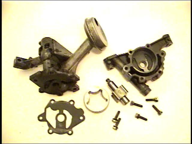
Clockwise from top left corner:
– Main body of the pump
– Rotor housing
– Bolts
– Inner rotor
– Outer rotor
– Gasket
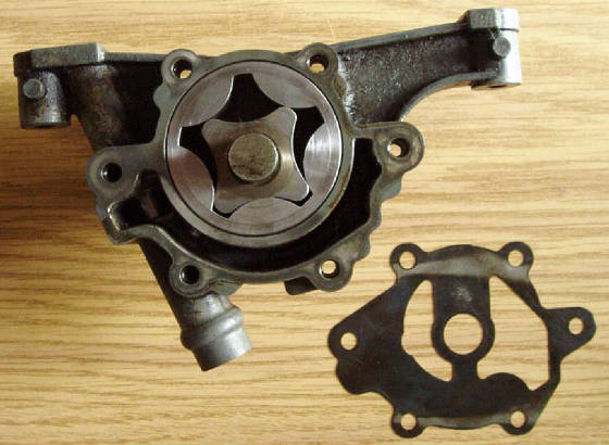
Four parts that get worn out:
1 – Rotor housing – this is seen on the picture as light color discoloration inside the cavity. As the part rubbed against the rotors that spun inside, the outer layer of the cavity lining got shaved off.
2 – Rotors – both inner and outer rotors get to be worn especially at the sides. As mentioned one side of each gets to rub against the housing cavity. Other side of each gets to rub against the gasket.
3 – Gasket
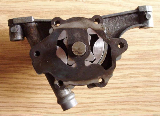
Shown above is the position of the rotors inside the housing. Both spin about own center, counter-clockwise. The shapes are matched in such manner that three cavities that are created are mutually liquid tight avoiding leakage and consequential low oil pressure. Once the gasket is placed on top, the biggest cavity creates a chamber bearing the brunt of oil delivery. The cavity on the right is shown in the position of creating suction. After the oil is replaced during the change, the suction is pneumatic during first few cranks of the engine. It is obvious that suction is created – spinning counter-clockwise this cavity is expanding while turning into the position of the biggest one on top. As the rotors turn, the biggest cavity contracts while turning into position of the cavity on the left, expelling the oil.
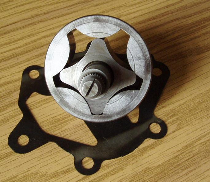
Shown above is covered rotor cavity by the gasket that precedes main oil body during assembly. Top rotor cavity is fully enclosed providing liquid tight chamber for oil translation within the pump.
On the condition of the parts . . .
Scored rotors must be replaced as they are incapable of provision of desired oil pressure. The rotors shown below are scored as well as worn to the point of being narrower than specifications call for. The rotor shaft having been grabbed could be moved by alternating it forward and backward within the pump before the disassembly.
The rotor housing must be replaced as well. The chain that pulls oil pump sprocket creates torque about the point that sits the butt of inner rotor within main body of the oil pump. Pulling the axis up, the chain forces the rotors to rub more against bottom half of the housing creating clearance with time.
The gasket must be replaced as well, it is intermediate part that participates in movement. It may be noted that sealing of the chamber created on top of the housing may be imperfect as the gasket provides small openings on both ends of the chamber. Designing custom gasket that ensures good coverage of that chamber by 1/32 of an inch may be interesting idea.
Pump removal . . .
I used this technique by myself a couple of times on the street in order to expose and remove oil pump of m30 in e34:
1 – Set the engine at TDC of cylinder #1
2 – Disconnect the exhaust by removing the hangers at the resonator and the muffler.
3 – Drain the oil.
4 – Disengage connectors for these sensors – oil pressure, idle control valve, coolant level.
5 – Dismount coolant expansion tank and push away to the left.
6 – Remove the plate that supported coolant expansion tank.
7 – Remove top nuts from engine mounts.
8 – Raise the car onto jack stands supporting at front mounting points.
9 – Disconnect exhaust at transmission.
10 – Remove the bolts that mount oil pan to transmission. Regular 8mm socket will do.
11 – Remove 10mm bolts along the perimeter of oil pan.
12 – Disengage the connector for oil level sender.
13 – Disengage steering pump from its bracket and push away to the left.
14 – Remove steering pump bracket.
15 – Remove bottom nuts from engine mounts. KEEP the mounts in place.
16 – Use the jack under front cross member to raise the car.
17 – Remove jack stands, placing one to support the engine directly under the engine mount area (for the bracket of air conditioning compressor).
18 – The jack stand should be extended about a foot and a half for sufficient room.
19 – SLOWLY lower the car, observing placement of compressor bracket and coolant expansion tank. The engine should not move too much to the side as the car is lowered. Lower only far enough for the engine to stop moving with respect to the car. The jack must be under cross member supporting the car. Lift just a bit to make sure that the car’s body does not recline on the engine BUT is fully supported by the jack.
20 – With enough extension of jack stand the engine rises with respect to the car providing enough room to remove oil pan through minor maneuvering.
21 – Lower the oil pan.
22 – Slowly raise the car using the jack at cross member. Watch for engagement of engine mounts with engine stands.
23 – Remove jack stand, place both jack stands at front mounting points, and drop the car on them.
24 – Undo the nut that holds oil pump sprocket, and slowly pull the sprocket off the rotor shaft.
25 – Undo 3 bolts that secure oil pump to the engine, finalizing removal of the sprocket off the rotor shaft.