Article by: Gerry at PhoenixMotorsport
Article applies to: all e31, e32, and e38 BMW models with the M7x engine.
Unfortunately, I need to apologize before I do this post because I did not keep stopping during the procedure to take photos. There is so many nuts and bolts to attend to, I did not keep stopping whilst “On a roll” and forget where I was, and lose concentration so there is a big hole in the middle with text but no pics, but here goes.
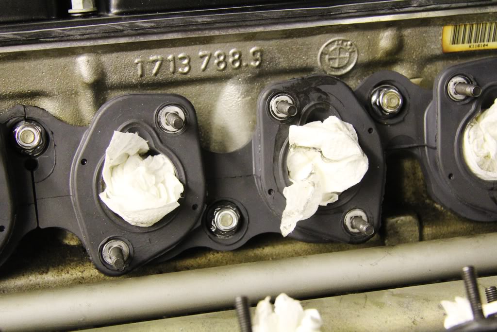
Firstly, clean the intake flanges on both cylinder heads and slide the 4 new gaskets onto the studs . . .
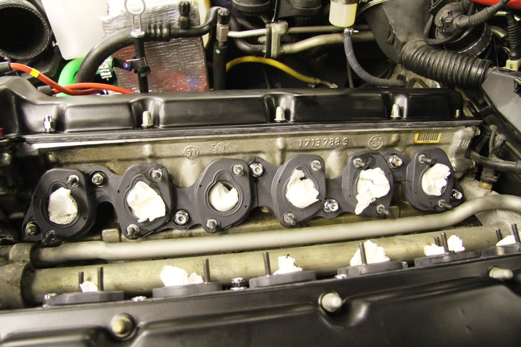
and loosely fit 10 new M8 flanged lock nuts and four of the original studs on the right hand front and left hand rear 4 studs.
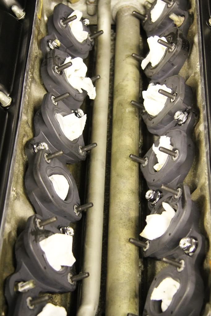
Next, torque all 14 fasteners up to24Nm in a cris-cross pattern to pull the flanges down uniformly.
Here you can see the raised sealing lip absent from the gaskets that were removed.
The front and rear engine lifting eyes can now be refitted to the front and rear 2 studs on each side, again with 4 new lock nuts. The engine is now ready for the manifolds.
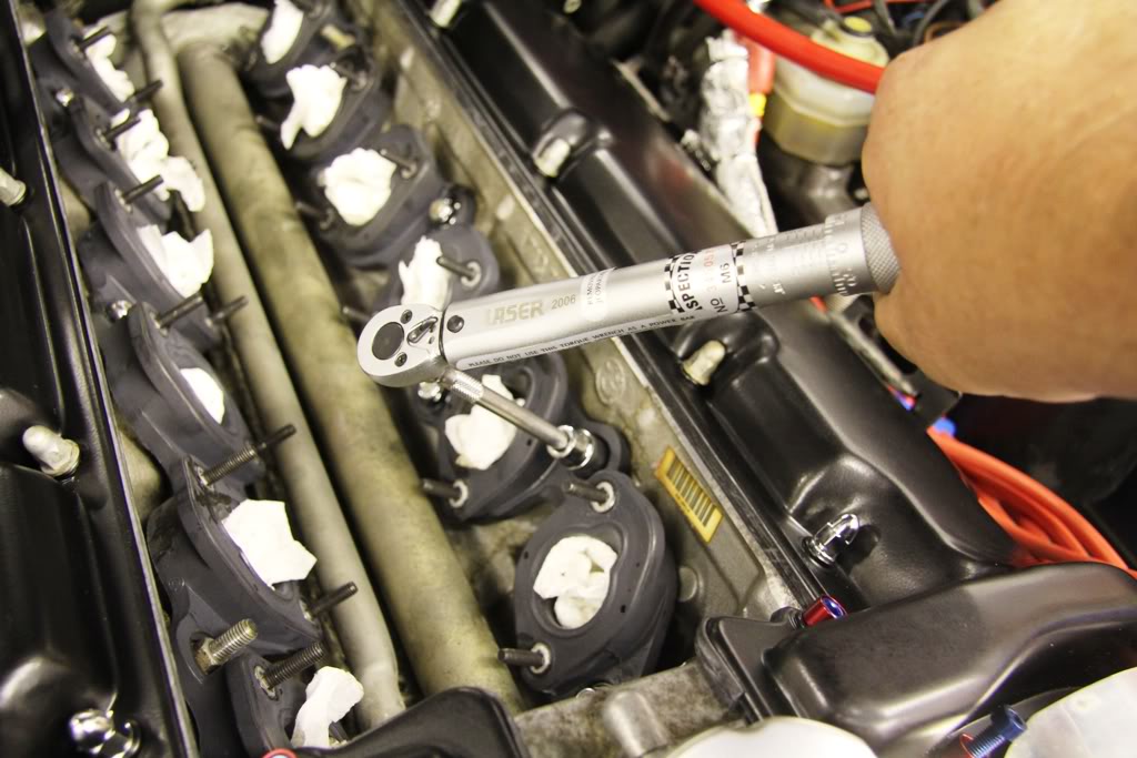
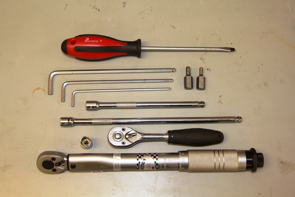
The only tools I needed to refit the manifolds is shown below. Note the “wobble” 1/4″ drive extensions and the thin wall 1/4″ drive 10mm socket, together with a set of 3 hex keys (as I use cap head bolts) a screwdriver and a 1/4″ Drive torque wrench.
After refitting the tubular return fuel line (which I am not using), you can slide one manifold into position on the greased intake studs and loosely start 12 of the M6 loose flange nuts, which I did all by hand with no access difficulty. Then slide the other manifold over its greased studs, jiggling the first manifold about on its loose fixings until it is flat against its gaskets. Next, grease the inside of the 10mm socket and using it on the end of the longest extension, stick the remaining nuts in the greased socket and feed the extension through the manifold and get all the remaining 12 nuts started. I used a small pen torch to aid in this and did the whole lot in under 5 minutes. Then go round all 24 nuts and “nip” them just to biting point with the 1/4″ drive ratchet. Then go around the whole lot again with the torque wrench and tighten to10Nm.
NOTE: DO NOT fit the support/insulation seals under the manifolds before you fit the manifolds as you need to access between the manifold and cam covers to access the lower nuts.
NOW you can slide the support/insulation seals from the outside, between the cam covers and the plenums and refit them with the three M5 bolts.
You can now refit the 2 fuel rails by greasing the “O” ring seals on the bottom of the injectors and lining them up carefully working from one end to the other and firmly pushing them down into the manifolds, securing with the two M6 bolts through the rail, into the manifold.
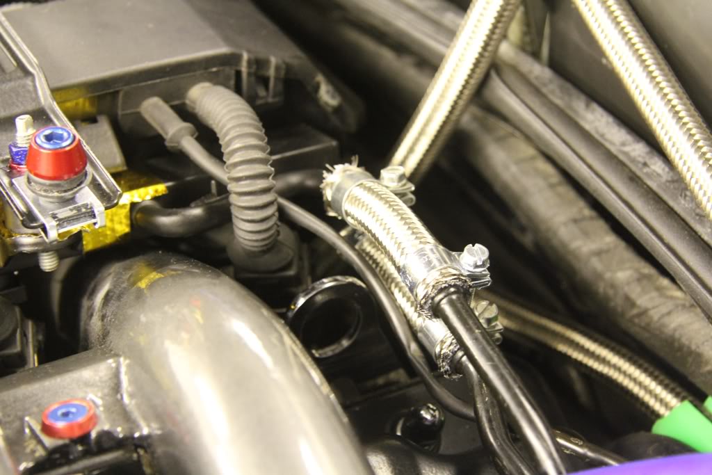
You can now refit the front 2 flexible fuel hoses from below the front of the fuel rails, under the fuel pressure regulators, (not fitted on my car) . . .
and at the rear of the rails on the supply lines.
You can now lower the engine loom into the valley between the injector rails and clip it down into position.
You can now refit the 10mm plastic nut at the rear of the loom trunking and then refit the 2 bridges.
You can now plug in the 12 injector looms.
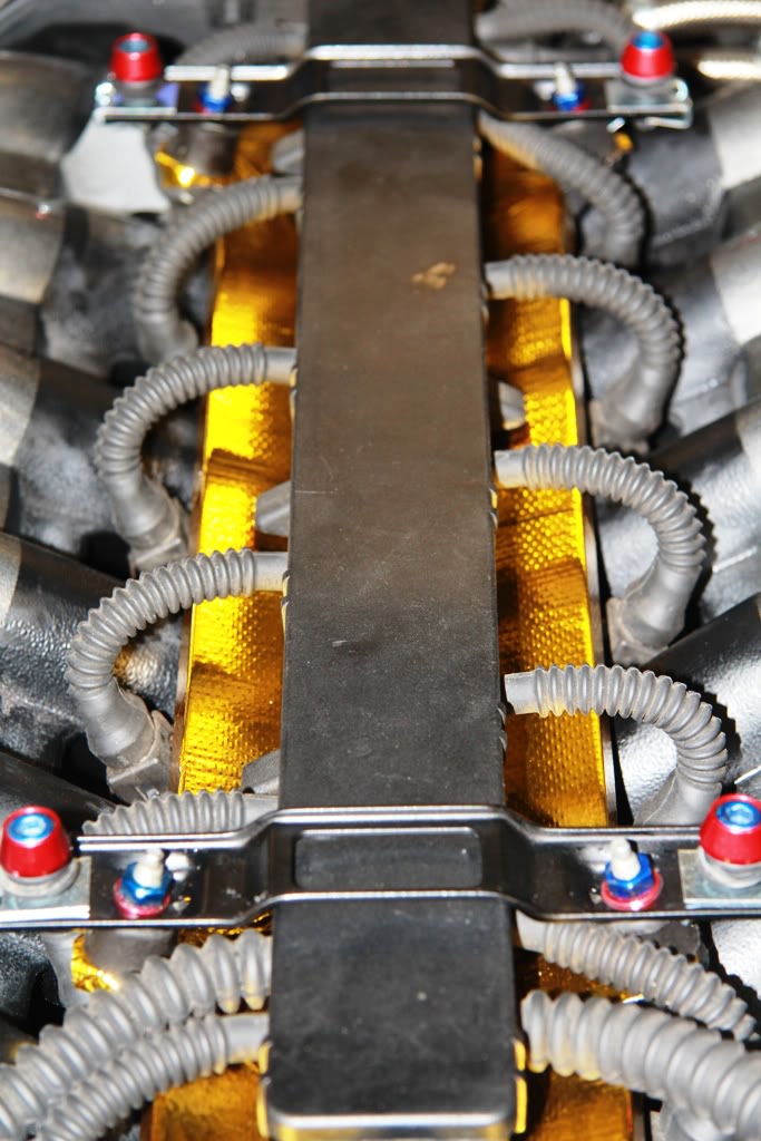
I have modified my bridges as seen here so that I can fit the sound hood with M6 bolts instead of cross-head self-tapping screws by flattening the hole where the screw went, drilling it out, powder coating the bridge and then fitting M6 chimney nuts in place.
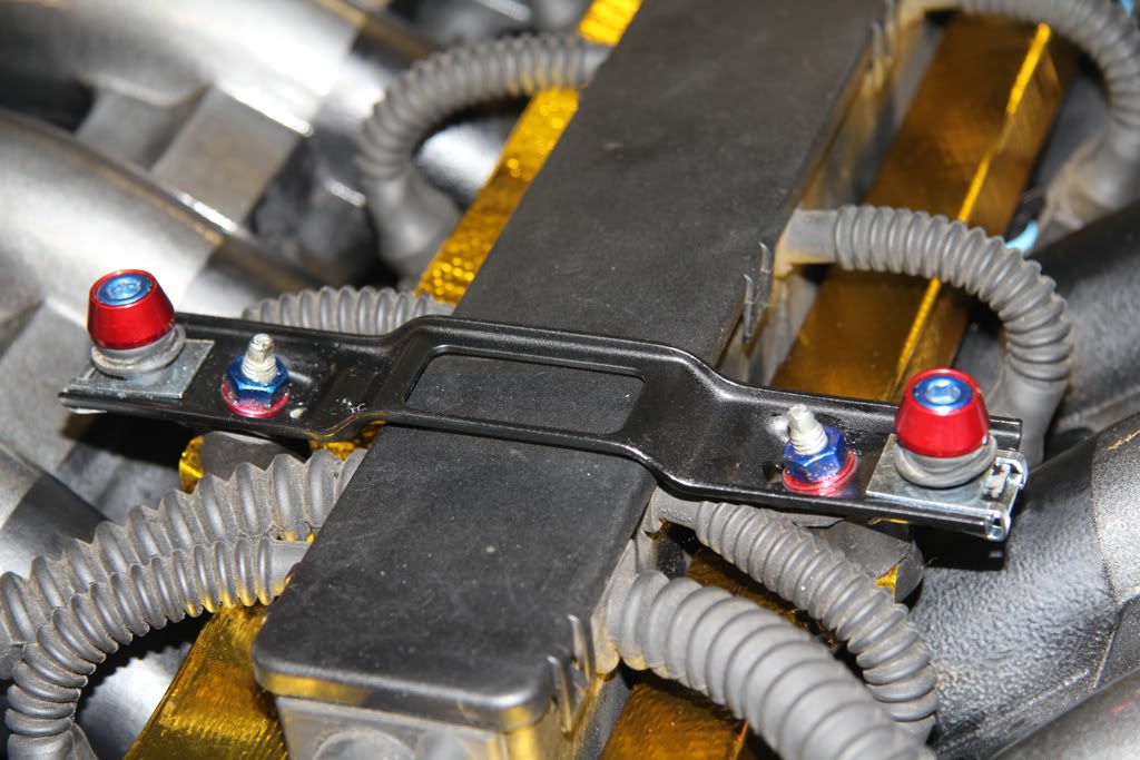
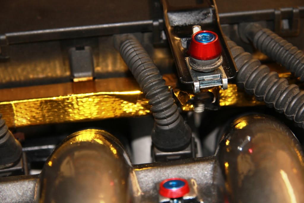
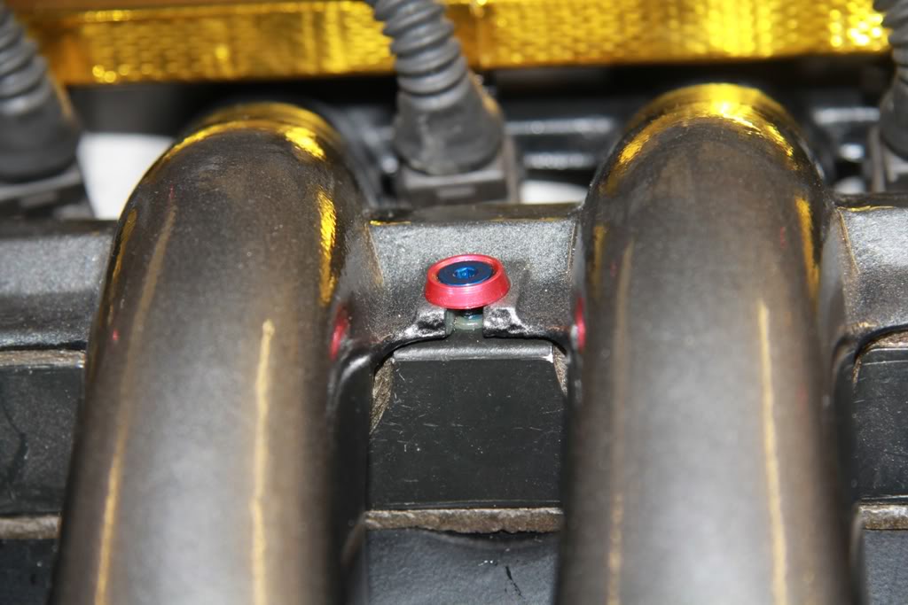
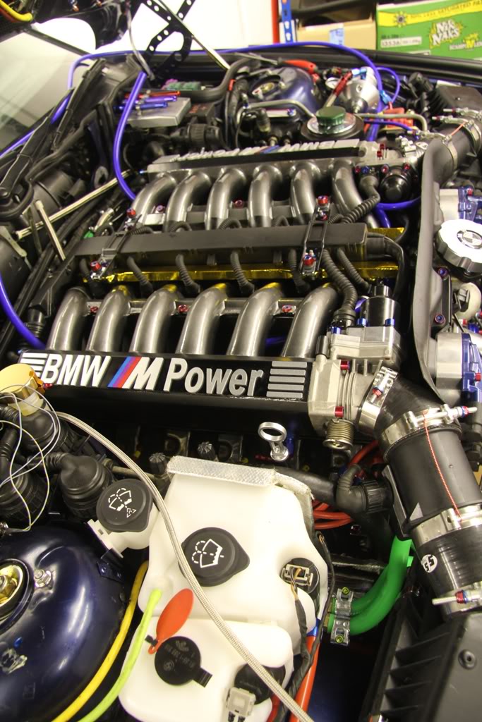
You may have noticed that my fuel rails appear gold and this is because they are thermally wrapped in Reflect-A-Gold.
http://www.designengineering.com/cat…r/reflect-gold
Now you can secure the alternator wiring tube and the HT lead trunking (not fitted on my car) to the left hand manifold as not seen here in this out of focus shot. 
I do not use the stock lead trunking A, because it causes lead failure and B, because I have 8.5mm leads that will not fit in it anyway! So my leads are tidied and clipped well away from the manifolds here on the left . . .
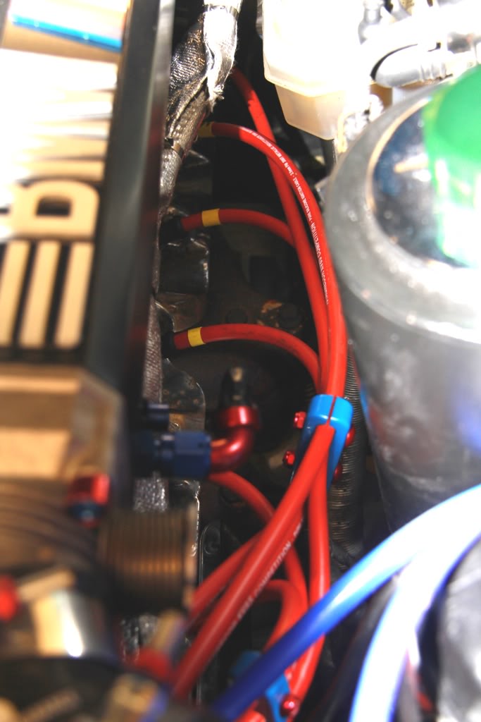
and here on the right . . .
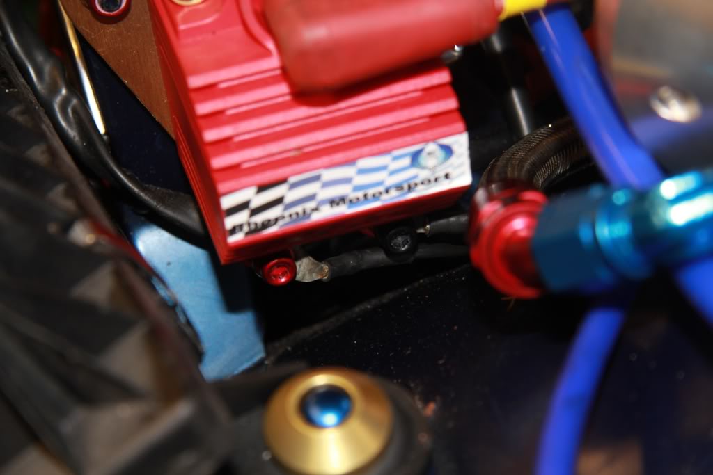
Wiring now needs to be reconnected to the left hand coil . . .
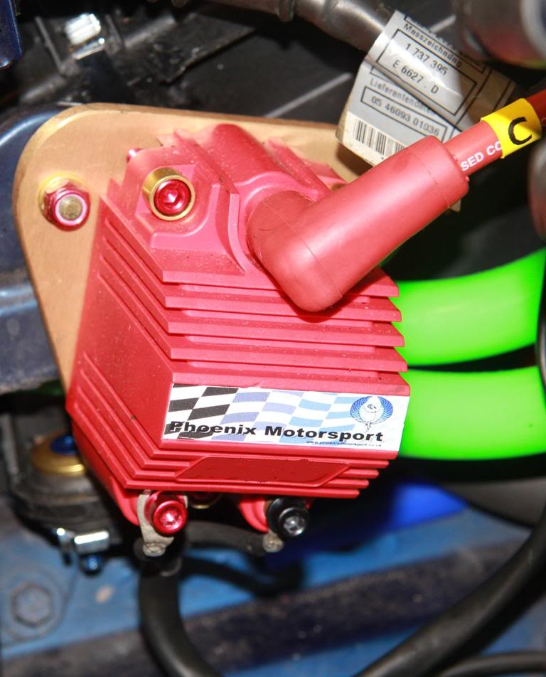
and the right hand coil.
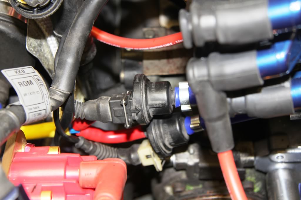
the two vent solenoids on the right . . .
the alternator and the oil level sensor on the sump on the left, and the diagnostics socket can now be refitted.
You can now refit the throttle bodies using new gaskets, remembering to refit the hoses before doing so as access is impossible once the bodies are bolted up. You can now reconnect the four multi-plugs under the oil filler cap seen here although this shot shows the routing of my fuel lines.
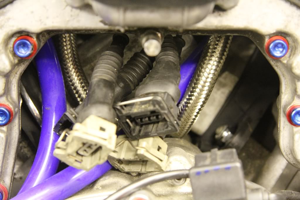
but shows the connectors before the mounting plates are fitted and the connections made.
You can now install the Mass Airflow Meters and connect them to the two remaining connectors from that engine loom here on the left . . .
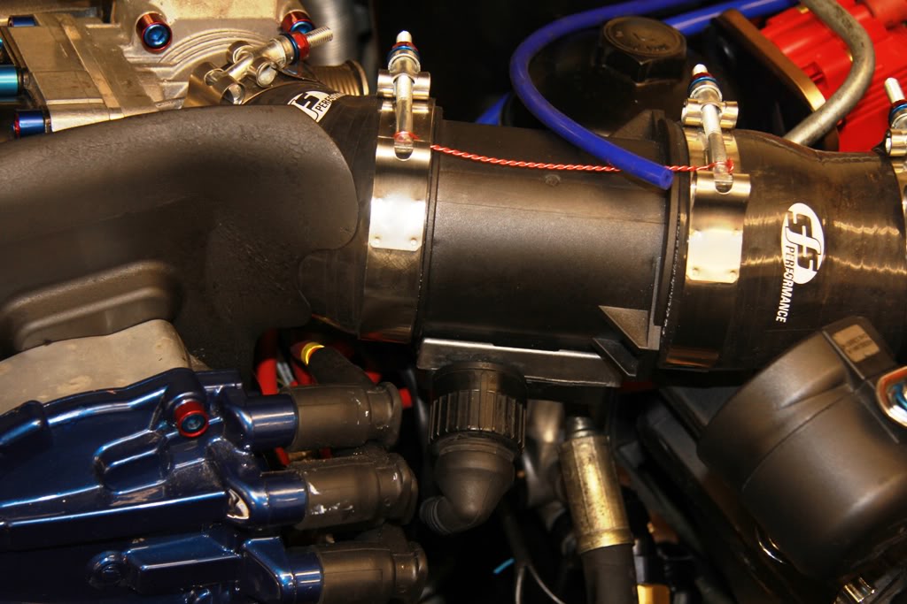
and here on the right.
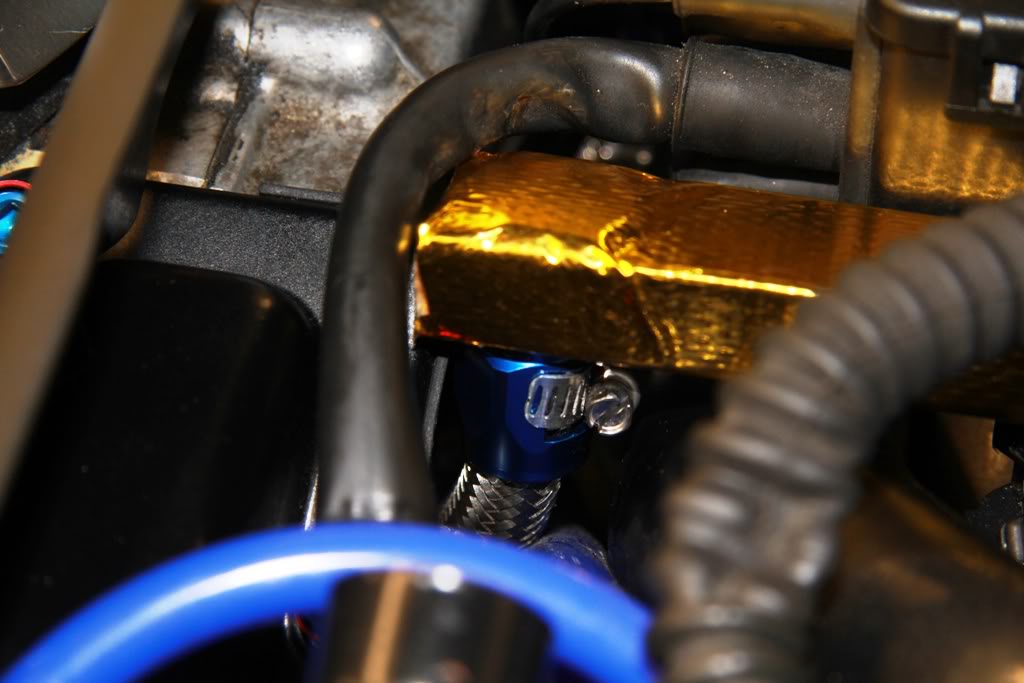
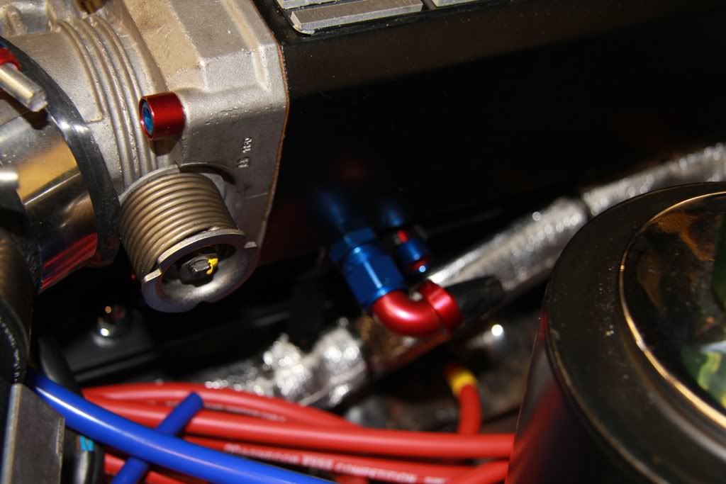
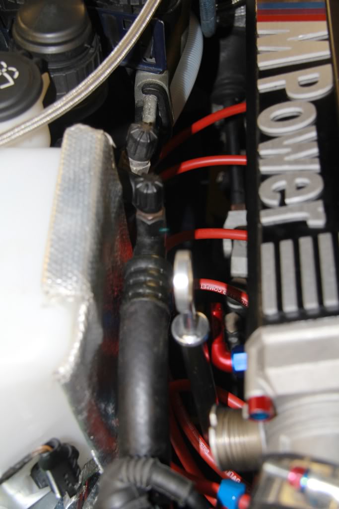
Here, my fuel lines follow the inner left hand wing behind the auxiliary water pump and brake master cylinder . . .
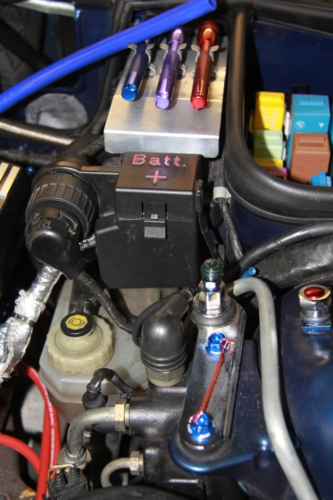
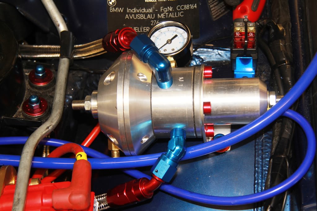
and attach to the standalone fuel pressure regulator.
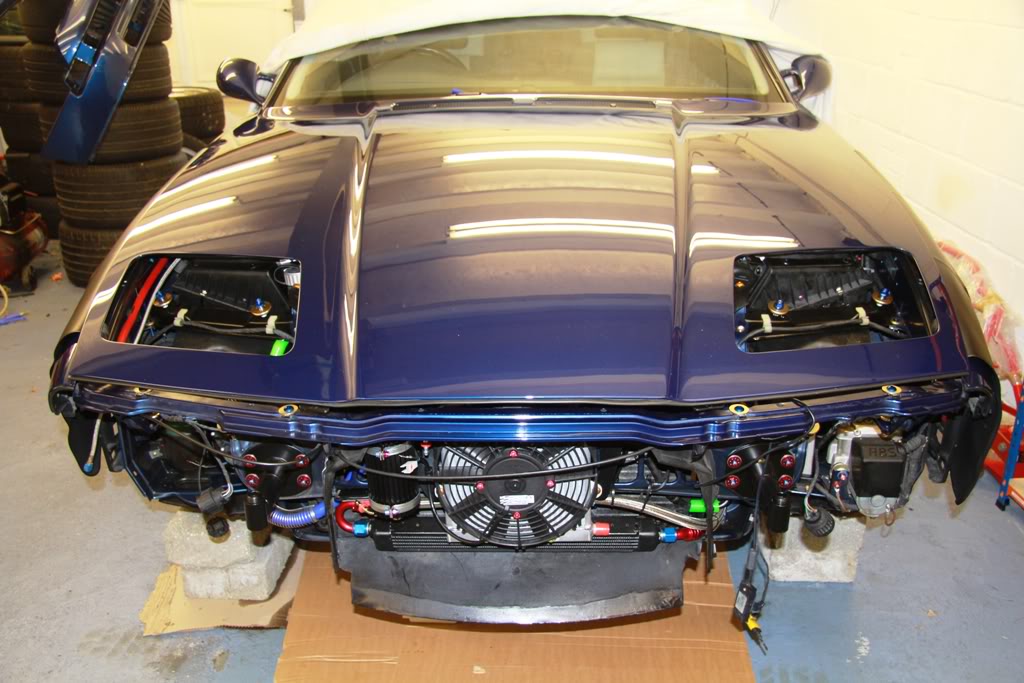
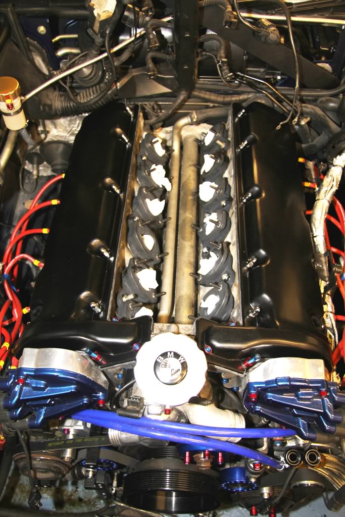
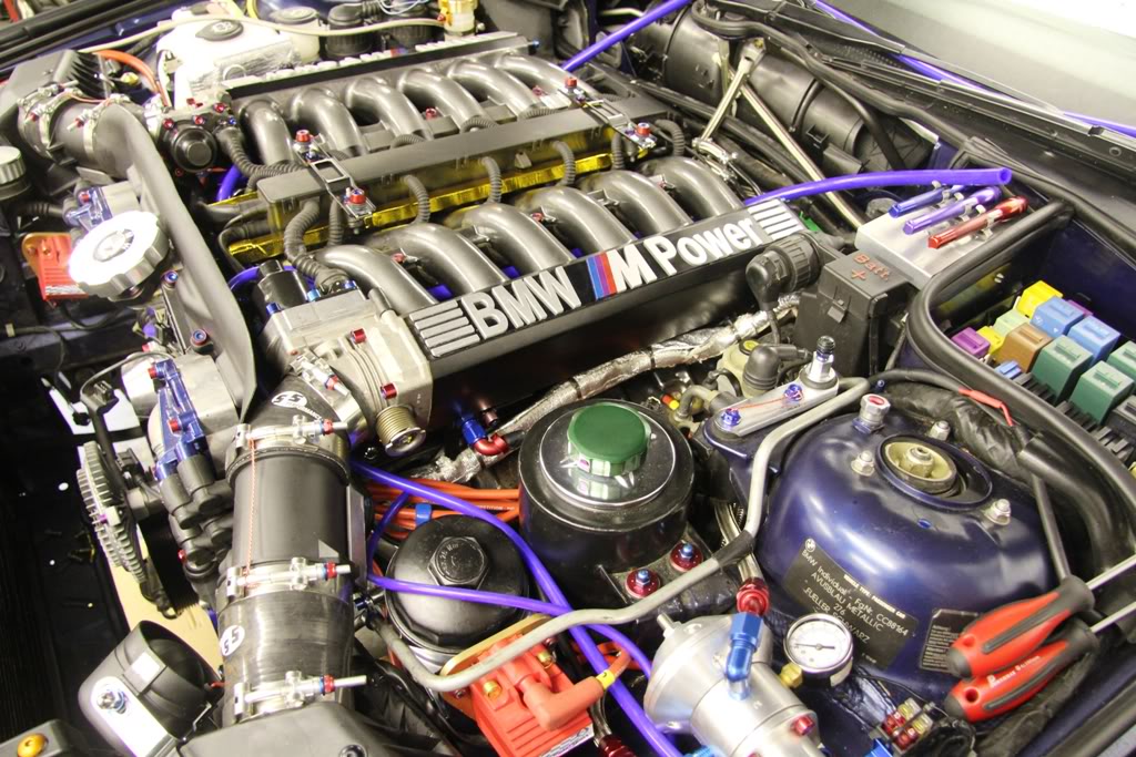
So here is the view just 2 hours from the very first photo

So until next time . . .