Article by: jmciver
Article applies to: written for the E36, but applicable to all BMWs.
This is where I will control some of the electronic “toys” in the car. Items controlled here include the radar detector, laser jammer, camera and nitrous system. It also houses the display for the tire pressure monitoring system.
DISCLAIMER:
This modification is to be followed and used at the sole risk of the individual performing it. When performing any modifications, there will always be the risk of damage to the car.
MODIFY AT YOUR OWN RISK. Read the procedure carefully and be sure that you feel comfortable with the modification before you begin.
Now on to the fun stuff!!
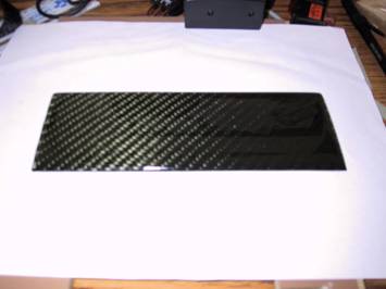
Carbon Fiber Face Plate:
First, I started out with a blank carbon fiber face plate. I purchased this piece from MK Autosport. It was originally designed to house three 2 1/16″ gauges as part of a gauge kit, but I was able to get it uncut.
This piece is already cut to the right size for the area below the OBC.
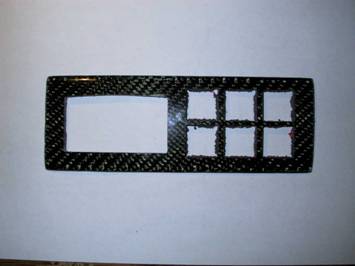
Machined Face Plate:
Next, I took the face plate to a machine shop to cut the holes for the switches and Smartire display. I could have used my Dremel tool, but the cuts would not have been as precise.
What can I say, I can be a bit of a perfectionist at times! The rough edges you see are from the adhesive material that came on the back of the face plate. T
hey will not be visible when the switches are in place.
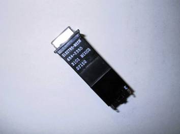
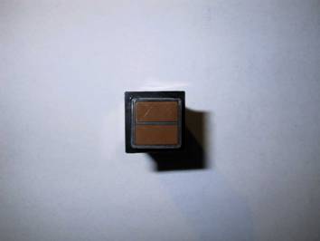
The Switches:
Here is a shot of one of the switches that I used. As you can see, these are not the average switches you find at the local auto parts store or Radio Shack.
I purchased them from a company called Electro-Mech Controls.
They are industrial type switches and were not cheap, but we won’t go into that!!
Front View of Switch:
On this front view of the switch you can see how it is divided in half. It will become obvious why I chose this configuration in later pictures.
I also had amber filters put inside the switches to match the instrument lighting.
One good thing about these switches is that I can change the entire configuration if I wanted without having to remove the switch.
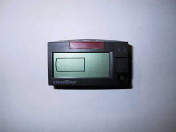
Tire Pressure Monitoring Display:
Here is a shot of the tire pressure monitoring display. This system is pretty cool.
It constantly monitors tire pressure and temperature when the car is moving.
It also has programmable warnings when the tires drop to a certain pressure or pressure deviates from a certain value.
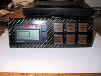
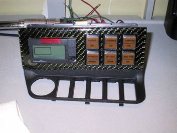
Assembled Control Panel:
This is the control panel assembled prior to installation.
You can also see the function of each switch as identified by the writing on it.
The switches and the display will also be backlit when the rest of the interior illumination is on.
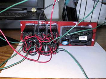
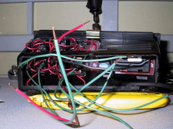
Wiring and Adhesive:
I used some hot glue to keep the components in place.
Each component had a snug fit in the face plate so the glue was more than adequate.
All of the wires were soldered to the switch terminals.
The cable for the tire pressure monitoring system plugs into the back of the display (not installed in this picture).
Sunglass Holder Installation:
Here you can see a rear view of the sunglass holder with the panel installed.
You can also see where I had to cut it in order to make the switches fit.
When you remove the back part of the sunglass holder as I did, the structural integrity of the sunglass holder becomes weaker.
If you attempt an install like this, I recommend you only cut out the openings that are required.
That being said, however, everything went back together in the car just fine.
Sunglass Holder Installation:
To hold the panel in place, I used the 3M adhesive that came on the back of the face plate.
This actually worked out better than expected.
Just be sure to clean the adhesion surfaces thoroughly for maximum adhesion.
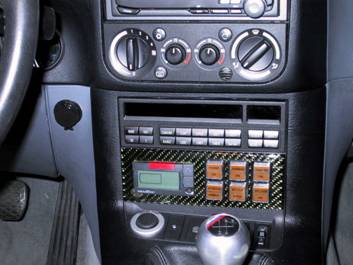
Final Installation:
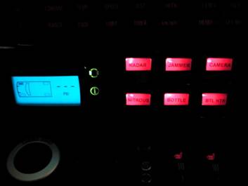
This is the panel installed in the car with everything back together.
One concern I had about this install was not being able to get the OBC out without peeling the panel away from the sunglass holder (to get to that little hole under the OBC to push it out).
Well, I found out that you can take the OBC out by gently using a flat head screwdriver and prying it out from above the OBC.
That is good in case I ever need to get back there again. In case you can’t see what the switches control, the upper three control the V1, laser jammer and camera.
The bottom three control the nitrous system, specifically, the bottle opener, bottle heater and system arming switch.
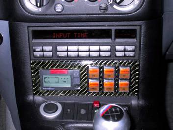
Illumination:
Here can see what the illumination looks like, both in the daytime and at night.
I tied the lights of the switches to the light circuit of the car (so they come on when the instrument lights come on and can be dimmed).
I used the wire that was originally used to illuminate the lighter socket since it was the most convenient one.
If a particular component is on, the top and bottom half of the switch will be illuminated to indicate the component is energized, regardless if the instrument cluster lights are on.
In the bottom picture you also get a good shot of the tire pressure monitoring system when illuminated at night.