Article by: Adam B. Hocherman
Article applies to: all BMW e36 M3 models (and probably others).
Changing The Brake Pads On Your E36 M3 Coupe
Changing the brake pads on your E36 M3 is a great first project if you are looking to foray into the world of home auto-repair. This procedure is accessible, requires no special tools and is almost foolproof. If you’ve been shying away from attempting this procedure because you’re afraid to bleed the brake system you’re in luck – you don’t have to bleed the brakes to change the pads. For those that are unfamiliar with the phrase “bleeding the brakes”, this is the procedure by which trapped air bubbles (which reduce braking efficiency) are removed from the hydraulic system.
The brake system on your car is a closed, dual-circuit hydraulic system with 4-channel ABS (for an excellent schematic see Bentley, Figure 3, p. 300-3). I was unable to confirm this in Bentley (please e-mail me if you can confirm this hunch), but I imagine that each of the two dual circuits is responsible for one front and one rear brake, thus maximizing fail-over capability in the event of a failure in one circuit or the other. The front brakes in any car are responsible for 70% of total stopping power (due to weight transfer in the vehicle under stopping conditions . . . think about how your chest is pressed into the shoulder belt in an emergency stopping condition). As such, you would rather lose one front and one rear brake in the event of a failure than loose both fronts.
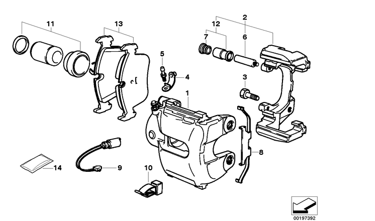
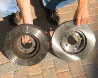
The brake pedal in your M3 is connected directly to the master cylinder. Hydraulic lines run from the master cylinder to the ABS unit and then to each of the wheels. The calipers in your M3 are a single-piston arrangement. Rotors in the M3 are beefier than in other 3-series models and are directional (which means that there is a right and a left, which is apparently not true for the stock sedan).
Before proceeding with this procedure it is important to understand a little bit about how the brakes in a car work. I’ll spare my audience a lengthy discussion about how hydraulic systems work (fundamental to the operation of your brakes) but suffice to say that a small force (your foot) applied over a large area (the master cylinder) translates to a tremendous force produced over a piston of smaller diameter (at the caliper). If memory serves from my days as an automotive engineer at Cornell University, a very simple formula governs this relationship:
F1A1 = F2A2
or
F2 = F1(A1/A2)
where:
F1 = Force at the pedal
A1 = Area of the master cylinder
F2 = Force at the caliper
A2 = Area of the caliper piston
Looking at the second arrangement of this formula it is easy to see that if the area of the master cylinder is, say, four times the area of the associated caliper cylinder, the force applied by your foot will be four times as great at the caliper piston. Any who, I’ll have to look this up when I have a moment.
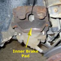
More important than the science is a basic understanding of some of the more counter-intuitive elements of this system, visible to the eye of the layman. The two brake pads (one outer, one inner) on each wheel form a sandwich with the associated rotor. The outer pad floats freely (it is “connected” rigidly to the car) and the inner pad clips to the inside of the caliper cylinder. The three components of this sandwich are constantly in contact with one another. Even when you are not applying pressure to the brakes, the pads rub on the rotor. This arrangement gives you two things. First, it allows for instantaneous braking reaction when you step on the pedal. Second it permits pad and rotor wear to be compensated for automatically. As these parts wear, the piston simply extends slightly further at its neutral point which keeps the sandwich in tact regardless of degree of wear. This means that no matter how worn your pads and rotors (except, perhaps, in extreme conditions) you will always have the same brake feel and stopping capability. Do not expect that your car will “brake like new” when you are done replacing your pads. If your car has mushy brakes or is experiencing some other braking related problem, you should look into it right away – it’s probably not your pads.
Before you get started you should think about what type of new pads you’d like to put on your car. Different pads are made of different compounds. Some wear more quickly (and/or produce more brake dust), but provide greater stopping power. If you are not a serious weekend racer I recommend using the OEM pad or a suitable replacement. I choose a set of OEM-style (I’m not sure if these are the actual OEM pads or not) Pagid pads which I purchased from All OEM BMW Parts for about $45. Bavarian Motorsports has a nice little write-up, that you may find interesting, if you want to learn more. You should also take a look at my brake pad FAQ.
For this procedure there isn’t even any prep to do the night before you begin. If you are planning to do front rotors at the same time you should soak the caliper carrier bolts (two on each side) with penetrating oil the night before you begin. These bolts were a b-tch to remove. Make sure you’ve thoroughly read the procedures you are about to perform before you begin, so you know what you are getting into. I’ve provided a full tool and part list which lists the items you will need. I’ve also performed a cost analysis for this procedure.
Ok, enough chalk-talk. Let’s get started.
Step 1: Remove Front Wheels
With the car on the ground loosen the five wheel lugs (on both sides) using either your factory wrench or a 1/2″ driver with 3″ extension and (19mm?) socket. Raise the front end of the car (refer to front jacking procedure) and remove the wheel lugs the rest of the way.
Remove the front wheels.
Step 2: Remove Brake Anti-Rattle Clips
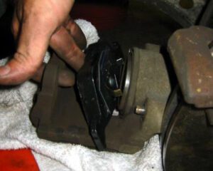
The brake clips (shown here being reinstalled) are easily removed using a pair of screwdrivers. Pry one screwdriver between the hub and clip (where my fingers are holding the clip in Figure 3).
This frees the two little catches (see Figure 3) and enables you to use a second screwdriver (wedged against the caliper) to pry the clip towards you and off the caliper. Best to use gloves and safety glasses here as these clips can come off with like a spring.

Step 3: Remove Caliper Guide Bolts
Reach behind the caliper and carefully pry out the two small rubber dust caps (see Fig. 4) using your fingernails.
This reveals the two 7mm allen-head caliper guide bolts (Fig.4 below) which secure the caliper to the car.
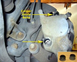
Remove the two guide bolts. Use a 3/8″ driver with a 7mm allen-head tip. This tip is available at most auto supply stores for about $5 and may actually be labeled a “disc brake caliper socket”. You may need to give the driver a light rap with your 3-lb hammer to brake the bolts loose but these were not difficult to remove.
Step 4: Remove Brake Pad Wear Sensor (Left-Front, Right-Rear Only)
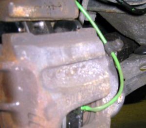
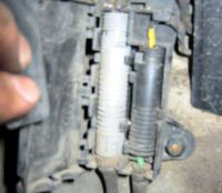
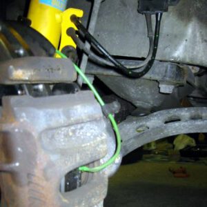
Your M3 has two brake pad wear sensors. The front sensor is located on the left-hand side and the rear sensor is located on the right-hand side. The front brake pad wear sensor runs from a wiring harness mounted to the inside of the wheel-well, around the strut (and secured by a clip mounted to it) and then back to the caliper. The small rubber cap on the brake-fluid release valve also serves to route the green sensor wire (see Figure 5).
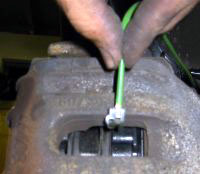
Using a pair of needle-nose pliers, carefully remove the ceramic end (Figure 6) of the brake pad wear sensor from the worn brake pad. This sensor does not necessarily need to be replaced, but the ceramic tip is fragile so it is a good idea to pr-preemptively buy an extra sensor in case you break the old one when removing it. If you choose to replace the sensor, the far end of it is located in the plastic harness box mounted to the inside of the wheel-well (Figure 7). On the left-hand side (pictured) this box contains connections for both the brake pad wear sensor (right) and the ABS sensor (left). To disconnect this end of the brake pad wear sensor, open the plastic box and snap the lower end of the wire out of the slot where it is seated. Next use your fingers, or a small screwdriver, to depress the plastic clips while pulling the harness apart.
Step 5: Remove Caliper
The calipers may be difficult to remove, particularly if your rotors are very worn (in which case they will have a lip). You can use a flat-head screwdriver, inserted into the brake pad wear sensor hole in the pad, to gently pry the pads away from the rotors. In practice, I found this difficult to do and didn’t have too much trouble simply removing the caliper without spending a lot of time on this step.
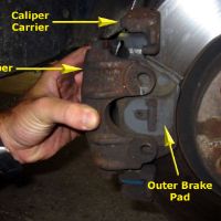
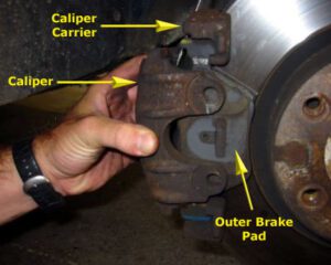
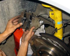
Gently pry the caliper (Fig. 8) away from the rotor. The inner pad is connected to the caliper and will come out with the assembly. The outer pad, shown in the photo, will remain in place. It is not secured in any way once you remove the caliper so take care not to drop it as you are removing the caliper. Once the caliper has cleared the rotor, simply lift the outer pad off of the carrier mount. The carrier mount is a separate piece of cast iron that is secured to the hub with its own two mounting bolts (see Bentley, p. 340-6, Fig. 8).
Note: This carrier need only be removed if you are replacing your rotors as well as your pads.
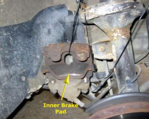
Finally, suspend the caliper (Fig. 9) from the strut assembly. Untwist a coat hanger and thread the wire through both the caliper and the spring. Ensure that no pressure is placed on the brake hose. Note: In the photo below, you can see the old inner brake pad which is still clipped to the caliper.
Step 6: Remove rotors
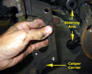
Unfortunately the rotor will not clear the caliper carrier, so the carrier must be removed. Unfortunately Bentley fails to mention this and is also annoyingly ambiguous when referring to removal of the caliper itself vs. the caliper carrier, which is a separate part between the steering arm and the caliper. I suggest ignoring Bentley for the moment (sorry Rob).
The carrier is secured to the steering arm using two (16mm?) bolts. Unfortunately these bolts are particularly difficult to remove. Make sure you give each of these bolts a solid squirt of penetrating oil the night before you begin this job. Use your 3/8″ driver with trusty breaker bar to tackle these bolts. The caliper carrier then falls free.
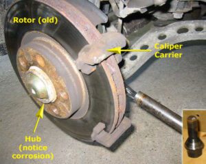
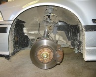
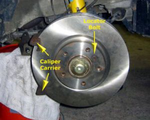
Although your stock M3 does not utilize a floating brake disc arrangement, the mounting setup is still quite interesting. The brake rotor is sandwiched between the hub and the wheel, all of which have five holes through which the wheel lugs pass. Once the wheel is removed, the only thing holding the rotor to the hub is a small locator bolt (see Bentley, p. 340-7, Fig 9). The locator does not bear a load and is provided simply as a convenience for properly aligning the rotor to the hub. You’ll notice that the wheel bolts have an interesting taper (see inset, Figure 1). These tapers serve to ensure that the hub-rotor-wheel assembly is always perfectly aligned. When the brake pads clamp the rotor, the five wheel bolts are completely in shear. The tapering ensures a perfect fit such that all five bolts always bear the load evenly. There is never a lateral force applied to the brake rotor. As such there is no need to affix the rotor to the hub. In fact, even if you lost the rotor locator bolt, it would be of little consequence save a bit of extra frustration when you go to mount the new disc.
Remove the locator bolt using a (5mm?) allen key. If you find that this bolt is corroded, a light tap with the 3-lb hammer should break it loose. If the bolt is really corroded and won’t budge, don’t force it – it will shear if you’re not careful. Use some penetrating oil to loosen the bolt.
The old rotor will likely be corroded to the hub. Working from the rear of the hub, place your breaker bar against the back of the rotor (at the outer edge) and give a quick rap with the 3-lb hammer. The rotor should fall free. Although I can think of better uses for a screwdriver, we were also successful by placing the handle of the screwdriver against the back of the rotor and giving a quick rap to the tip.
Step 7: Install New Rotor
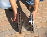
Installation of the new rotor is the reverse of removal. Be mindful to install the rotors on the correct sides – there is a left and a right. According to Bentley, “M3 models use directional brake rotors and must be installed on the proper side. Part numbers are cast into the rotors. A part that ends in an odd number is a left rotor. One that ends in an even number is a right rotor.”
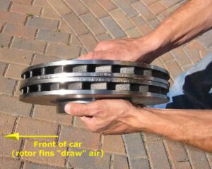
As a sanity check, note the direction of the fins in Figure 4, below. The installation direction of the fins is a little counter-intuitive. The direction of rotation of the rotors is such that the fins “draw” air, rather than “scoop” it. I was surprised to find that either rotor will fit either side, so this step is not “dummy proof”.
If you get the installation wrong your car will stop but the rotors will not cool properly and may warp prematurely.
Align the locator hole in the rotor with the locator hole in the hub and tighten the locator bolt (16 Nm, 12 ft-lb).
Replace the caliper carrier (see Figure 5) and tighten the two bolts to 110 Nm (81 ft-lb).
Note: I read this value off the table on page 340-6 in Bentley which states, “Front brake caliper to steering arm . . . 110 Nm (81 ft-lb)”. Of course, the caliper does not mount to the steering arm, the caliper mounts to the caliper carrier which mounts to the steering arm. I made the leap . . . proceed at your own risk. In reality there isn’t much risk of stripping here – you are securing two cast iron pieces with some serious bolts. None-the-less, don’t over-tighten!
Last, but not least . . . time for new brake pads!
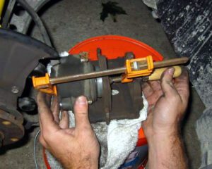
If your old pads were very worn (and of course they are or you wouldn’t be replacing them) you will need to compress the piston in order to have the new pads clear the rotor when the caliper is reinstalled. You can buy a special tool from any auto part store to do this but I found it very easy to perform this step using an ordinary wood clamp.
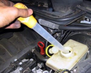
In order to avoid a potential mess, open up the brake fluid reservoir and use a turkey baster to remove 6-8 ounces of brake fluid (see Fig. 16). Put the fluid in a clean cup as you will need to replace it later.
Leave the cap of the reservoir off!
At this point it is helpful to locate something that the caliper assembly can sit on while you work with it. Matt and I used an overturned tar bucket for this purpose. Remove your make-shift caliper holder (coat hanger) and place the assembly on the bucket, again ensuring that the brake hose is not stressed in any way.
If you’ve already removed the old inner pad, temporarily return it to the caliper. Carefully center the wood clamp on the old pad (Fig. 17). Slowly tighten the clamp, easing the piston back into the caliper. You should be able to do this with little resistance. If you feel too much resistance, STOP, and recenter the clamp. Continue to compress the piston until only a few millimeters of the silver piston can be seen protruding from the caliper.
Note: If you just can’t get the piston to compress, here’s what you need to do. Open the rubber bleeder valve dust cap. While compressing the piston slowly open the bleeder valve. Have a receptacle handy as you will lose fluid from here. If you are careful to keep pressure on the pad while the valve is open no air will enter the system. If you are not careful and air gets drawn into the bleeder valve you will need to bleed the system. I did not have to open the bleeder valve, nor did I bleed my car’s brake system, so if you screw this up you’re on your own.
Step 8: Clean Piston (And Rotor, If Not Replacing)
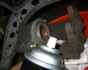
Using brake cleaner carefully spray the inside of the piston to remove any loose brake dust. Be mindful not to get brake cleaner on the rubber piston seal as it will degrade this part. Ensure that the slot that runs around the inner circumference of the piston (see Fig. 18) is free from debris as this is where the pad clip seats.
If you are not replacing your discs, use the brake cleaner to remove loose brake dust from these parts as well. If you are replacing your discs simply wipe the new parts down to ensure that there is no residual grease or oil.
Step 9: Apply Anti-Squeal
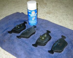
The cause of brake “squeal” is counter-intuitive. Brake squeal is not caused explicitly by the contact of the pad and the rotor. Rather, brake squeal is caused by micro-vibrations in the pad as a result of extremely high-frequency “catching and slipping” of the pad against the rotor. Application of brake anti-squeal paste or spray is similarly counter-intuitive. I’m not exactly certain how these magical products prevent these vibrations, but they do. The trick is to apply the anti-squeal product to the back of the new pads (the clip side, not the pad material side). I’ve seen many people recommend using BMW Plastilube anti-squeal paste (BMW part number: 81 22 9 407 103) but neither of the two dealers in my area carried it. I bought a canister of aerosol product from AutoZone and found it very easy to apply and effective, to boot.
Lay your new pads out on the ground (see Fig. 19) and apply a couple of coats of aerosol product to the back of the new pads. The product I used had a faint blue haze to it and after 10 minutes or so dried to a tacky finish.
Step 10: Install New Pads
The new pads are now ready to be reinstalled. There is no such thing as a “left” and “right” pad (unlike for the rotors). That said, there is an “inner” and an “outer” pad. The inner pad has a clip on it, the outer pad does not. Your box of new front pads will contain two of each. Clip the new inner pad to the piston – ensure that you have the orientation correct (see Fig. 20).
Step 11: Replace Caliper Assembly, Wear Sensor & Anti-Rattle Clip
Unlike the inner pad, the outer pad does not attach to the caliper in any way. Simply hold the outer pad in place with your hand as you slide the pad / caliper assembly back over the brake disc. See Fig. 21.
Replace and tighten the two caliper guide bolts (30 Nm, 22 ft-lb).
Reinstall the brake pad wear sensor being careful to properly route the cable as shown in Fig. 22. The cable goes behind the strut and then loops back around, through the closed rubber bleeder valve dust cap and back to the pad. The harness side of the cable snaps in place. Snap the cover of the harness box shut. The ceramic end of the wear sensor presses easily into the new pad.
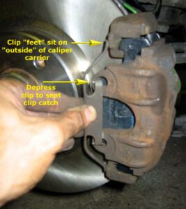
Replace the anti-rattle clip. Ensure that the clip “feet” sit on the “outside” (the side closer to the hub) of the caliper carrier. See Figure 23 below.
Step 12: Replace Wheel (Don’t Torque!)
Replace the wheel. Hand tighten the five wheel lugs.

Lower the car back onto the ground following the reverse procedure you used to raise it (see Proper Jacking Procedure). With the car back on the ground torque the wheel lugs (100 +/- 10 Nm, 74 +- 7 ft-lb).
Step 13: Replace Brake Fluid & Pump The Brakes
Replace the brake fluid you previously removed and close the reservoir tightly. Shut the hood. Pump the brake pedal several times to restore pressure to the brake system as the new pads seat.
Congratulations! You’re done!