Article by: Adam B. Hocherman
Article applies to: all BMW e36 M3 models (and probably others).
I’d like to thank my friend Larry Barbieri who donated his time and garage to help me with this procedure one brisk morning this past December.
This write-up outlines the procedure for replacing the rear pads and rotors on your E36-series M3. Performing the rear brake replacement is almost identical to performing the front brake replacement. As such, I have gone into slightly less detail than for the fronts. I recommend that before you begin you skim the details pertaining to replacement of the fronts and review the Brake Pad Intro and Brake Pad FAQ which I wrote previously. In addition, I’ve cross-referenced details to the front procedure where appropriate.
The following information depicts parts prices (of the time), tools, and torque values:
Prices:
| BMW Part Number | Description | Price | QTY |
| 34212227177 | Rear Rotor, Left | $45.00 | 1 |
| 34212227178 | Rear Rotor, Right | $45.00 | 1 |
| 34211157334 | Rear Replacement Pad Set | $35.00 | 1 |
| 34351181342 | Rear Brake Pad Wear Sensor | $8.00 | 1 |
| Tools: | |
| Floor jack | 7mm allen key socket |
| 16mm socket | Turkey baster |
| 17mm socket | Penetrating Oil |
| 18mm socket | Anti-seize paste |
| 6mm allen key socket | Safety glasses |
| e36 M3 Brake System Torque Values: | |
| Rotor locator bolt | 16 Nm (12 ft-lb) |
| Caliper guide bolts | 30 Nm (22 ft-lb) |
| Caliper carrier bolts | 67 Nm (50 ft-lb) |
| Wheel lugs | 100 +/- 10 Nm (74 +/- 7 ft-lb) |
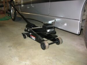
Step 1: Loosen Lugs & Jack Car
Start with the driver-side rear (which does not have a brake pad wear sensor). Loosen the lug nuts (17mm socket) while the car is still on the ground. Jacking (see the proper jacking procedure) the car with a hydraulic pump is a no-brainer and we were able to easily support one corner of the car at a time, using a single 3-ton jack stand. Adjust the stand to be just high enough to get the rear wheel off the ground. If you do not have a hydraulic jack review my proper jacking procedure and apply a similar methodology to the rear of the car. I highly recommend doing one corner at a time either way.
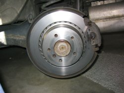
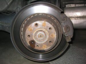
Remove the wheel to reveal the crusty old pads and rotors (see fig. 2).
Step 2: Apply Penetrating Oil
In preparation for removal, apply penetrating oil to the following bolts:
- Rotor locator bolt (this is the small hex bolt visible in fig. 2, above).
- Caliper carrier bolts (if you are also replacing rotors).
We used a foaming aerosol variety of penetrating oil this time which worked very well.
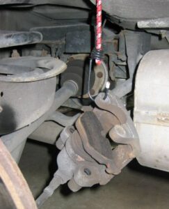
Step 3: Remove Anti-Rattle Clip & Caliper
Using your fingers, remove the two rubber dust caps that cover the caliper guide bolts (see also fig. 4 from the fronts procedure). Remove the two guide bolts using a 3/8″ driver with a 7mm allen-head tip. This tip can also be purchased as a “disc brake caliper socket”.
Tip From Larry: If you are not doing struts at the same time as rear brakes, it is difficult, if not impossible, to get a 3/8″ drive ratchet with the 7mm hex socket on it into the upper caliper guide bolt. When I did mine, I loosened the lower shock bolt (18mm) and slid the shock away from the trailing arm to get clearance. Don’t forget to torque that back down (77 Nm (57 ft-lb)) when you are done.
Using a pair of screwdrivers, remove the anti-rattle clip. My friend Larry has a knack for doing this with his bare hands, so you may try that as well. In either case, be mindful of your eyes.
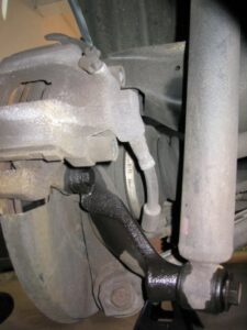
Using a flat-head screwdriver on the top and bottom of the caliper, carefully pry the assembly off of the rotor (see fig. 4, below). Note that the inner brake pad is held in place with a clip whereas the outer pad floats freely and may fall away. Hang the caliper from the car using a bungee cord or wire coat hanger. Since we replaced the rear shock mounts at the same time that we did the brakes were able to thread the far end of the bungee cord directly into the hole in the frame where the shock would be mounted. You will have to find an alternate means of suspending the caliper. It doesn’t matter how you get it done, just ensure that you are not putting any pressure on the brake line.
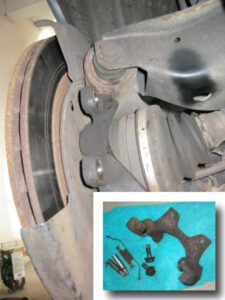
Step 4: Remove Caliper Carrier (For Rotor Replacement Only)
Using a 16mm socket and something with a nice long lever arm, remove the two caliper carrier bolts. Unlike the fronts, we had no problem removing these bolts. Another note; in general and if you have it available, a six-sided socket works better for tough bolts than the twelve-sided variety. Fig. 5, below, shows the rear brake assembly with the carrier removed. The carrier can be seen in the inset.
Step 5: Replace Rotor
Before doing anything else, locate the appropriate rotor for the side you are working on. THERE IS A LEFT AND RIGHT. The fins in the rotor “draw” air, rather than “scoop” it. Also, using brake cleaner remove any cutting oil or other greasy residue that may be resident on the new rotor from the manufacturing process (or your greasy hands).
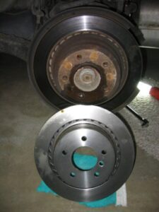
Using a 6mm allen key, remove the rotor locator bolt and set aside. Unless you’re very lucky, the old rotor will be corroded to the hub. Using first a rubber mallet, followed by a 3-lb hammer, rap the rotor from both front and back until it falls free. The less aggression you can use to remove the rotor the better, but don’t be afraid to have your way. The old rotor gets disposed of anyway.
Put the new rotor on and tighten the locator bolt using a torque wrench (note appropriate tension – see sidebar).
Step 6: Replace Caliper Carrier
Again using your torque wrench replace the caliper carrier and tighten the bolts appropriately.
Step 7: Remove Brake Fluid & Compress Piston
Using your trusty turkey baster, remove about a half-cup of brake fluid from the reservoir to prevent spillage. Leave the cap of the reservoir loose to allow air to escape while you compress the piston.
Leaving the old, inner pad in place for now, use a wood clamp and carefully compress the cylinder to provide room for the new, non-worn brake pads. Ensure that the clamp is centered – the piston should slide back easily.
Step 8: Prep New Pads & Reinstall Caliper
Apply your favorite variety of brake anti-squeal paste/spray/prayers to the the metal back of the pads. Using compressed air and/or a toothbrush with some brake cleaner try to clean up the caliper as much as possible being mindful not to get brake cleaner on the rubber gaskets, which will erode as a result.
Remove the old inner pad and clip the new one in place. “Hang” the new outer pad on its mounting point on the caliper and slip the caliper assembly back onto the rotor. Tighten the caliper carrier bolts using a torque wrench and replace the rubber dust caps. Reinstall the anti-rattle clip.
Step 9: Repeat For Passenger-Side Rear
Repeat this procedure for the passenger-side rear of the car. Note that the passenger-side rear brake assembly contains the brake pad wear sensor which will likely need to be replaced. Simply remove it using a needle-nose pliers and once you have installed the new pads press the new sensor in place using your fingers and/or a flathead screwdriver. The far end of the sensor clips into a wiring harness mounted in the wheel well. Note how the cable is routed before removing it. For more details about installation and removal of the brake pad wear sensor, please see the fronts procedure.
Step 10: Replace Fluid, Pump Brakes & Drive!
Pump the brakes 3-4 times to restore pressure to the system. Top off the brake fluid, if necessary, and close the cap.
Congratulations, you’re done!