Article by: Vinci
Article applies to: This guide specifically covers the process on a 1998 M Roadster, however, the process is nearly identical for all Z3s and many E36s (some differences exist for OBD1 cars).
This guide covers the process of removing the E36/Z3 transmission for the purpose of servicing and/or replacing the clutch and related items.
Torque specs have been intentionally omitted because of possible differences. Please refer to the Bentley manual for the values specific to your model.
Tools/parts:
There are many common tools needed for this job, so I will assume that kind of DIY’er that would take on this project will have those tools on hand. Below is a list of all the parts that I recommend that you have on hand, as well as some tools that I consider a little less common. Some of the parts listed may not be necessary, but make sense to replace, given the work it takes to remove the transmission. I have not listed part numbers in this guide, as they may vary between different models. I have, however, used the official names whenever possible so that it will be easier for you to look up those numbers on www.ShiftOEM.com.
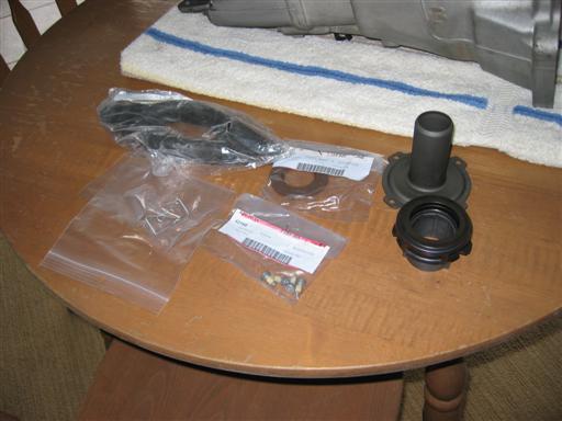
- Clutch kit (typically includes a clutch disc and pressure plate)
- Clutch release bearing (aka: throwout bearing, sometimes included in the above kit)
- Clutch bearing guide tube
- Clutch fork ball pin (fulcrum for the clutch fork)
- Clutch fork spring clip (holds clutch fork to the ball pin)
- Clutch fork
- Exhaust header output flange gasket (these are one-time use)
- Guibo nuts (these are one-time use, 6 total)
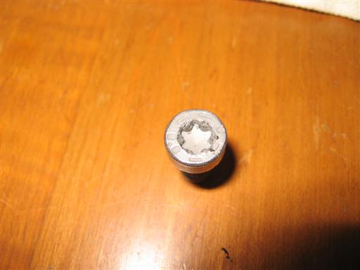
- External Torx sockets (sizes E11, E12, and E14)
- Various long socket extensions
- Clutch alignment tool
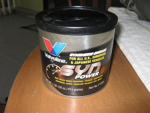
- High quality lithium grease
- PB Blaster
Tool/part notes:
- I highly recommend that you replace every fastener that you remove. Some will be rusty, some are one-time use, and some could be damaged in the process. You do not want to get stuck in the middle of the project because of a $0.56 nut. Ask me how I know. . .
- External Torx sockets are sometimes known as “inverted”, “female”, or “outside” torx by different manufacturers. Most sets will include the E12 and E14 that you need, but only Snap-On offers the E11, and only in their large set or by itself.
- This is an excellent time to replace your guibo and transmission mounts, if they are original or have a lot of mileage on them. They are inexpensive and have to come off anyhow.
- Don’t forget the PB Blaster. WD40 is NOT an equivalent. Blaster can get you out of a lot of binds in this job.
- Have several jacks on hand. I find that bottle jacks are really convenient for lifting the transmission and motor without getting in the way too much.
- An extra set of hands is invaluable at times. Have a buddy near by, even if for no other reason than to have them call 911 when you drop the transmission on your face.
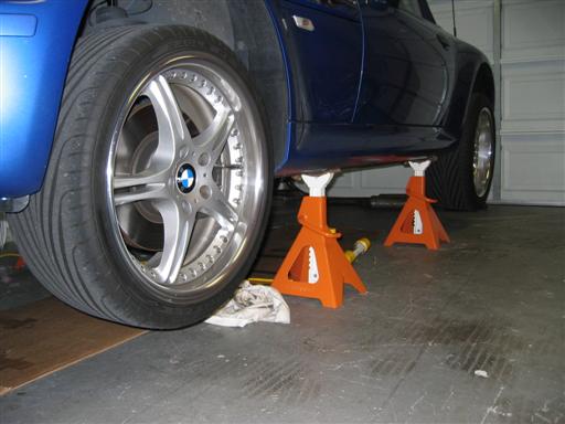
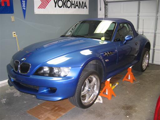
Step 1: Lift the car.
You will want as much clearance as you can get, so put the car up as high as you can on sturdy, stable jack stands.
I used 6-ton stands for their larger bases. Place the stands under the factory jack pads.
I ended up with around 18 inches of clearance under the car, due to limitations of my floor jack.
Being a fairly small guy, however, was perfect for me.
Be warned, you will not be able to get the transmission out from under the side skirts with less than that clearance.
Step 2: Prepare all the bolts that are to be removed.
Spray PB Blaster on every nut and bolt (front and back, when possible) that you will need to remove. This lessens the likelihood of rounding or breaking bolts. The exhaust bolts may need to be sprayed several times. Give the nuts/bolts a good half hour to soak before working on them.
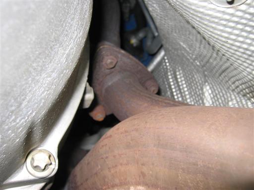
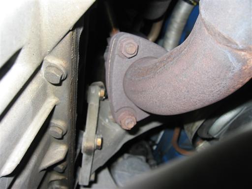
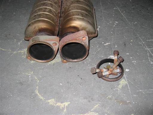
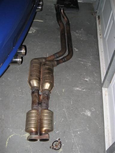
Step 3: Remove exhaust center pipes.
Start by removing the 6 nuts on the header output flanges (3 per pipe). Watch your eyes when pulling the pipes off the studs, as the gaskets shed a lot of glittery crap that would be bad to have in your eyes. When you wiggled the pipes free, they will rest nicely on the X-brace while you work on the rear section.
Head to the rear of the car and remove the two post-cat O2 sensors. Unplug the two sensors from the harness, located on the driver-side, at the edge of the heat shielding. You will then need to unclip the wires for the sensors from the heat shield as you head back towards the exhaust. When finished, you will have the ends of the sensors hanging freely. Now, just remove the sensors themselves from the exhaust pipes. You will need a 22mm wrench for this. You can leave the sensors in the exhaust is you want, but they are much less likely to be damaged if you take them out.
With the pipes unhooked from the headers and the O2 sensors removed, it is now time to disconnect the pipes from the rear mufflers. These bolts were very rusty on mine, despite every other fastener under the car being clean. You will definitely want to replace these. Using 12mm (nut) and 13mm (bolt) box-end wrenches, remove the 4 nuts and bolts (2 per pipe). Wiggle the flanges away from the place where the pipes join, and a pair of gasket rings will drop out (one per pipe). The exhaust center pipe should now be completely free. The center pipes are surprisingly heavy, but the front end of the pipe should still be supported on the X-brace. Take your time and wiggle the pipes free and set them some place out of the way. I chose to route the wiring for the O2 sensors up towards the front of the car to keep them out of the way.
As a side note, the replacement nuts for my mufflers were copper, whereas the originals were not. They function the same, but this was the first of many design revisions I noticed along the way.

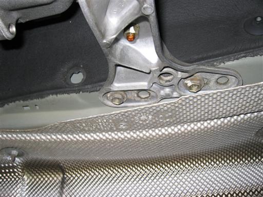
Step 4: Remove exhaust heat shields.
With the exhaust removed, you will have easy access to the heat shields. You will need to remove the shield along the passenger side so that you can remove the transmission brace (shown below). You will also need to remove the rear, center shield to allow access to the drive shaft and shift linkages. The heat shields are just dimpled aluminum, so be careful with them. They are held in place by round, stamped, “nuts”. You can remove these easily with a 10mm socket. Please ignore the O2 sensors in the 3rd picture. I didn’t take mine out in the way I described in step 3.
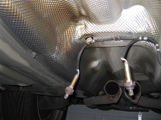
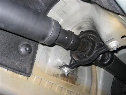
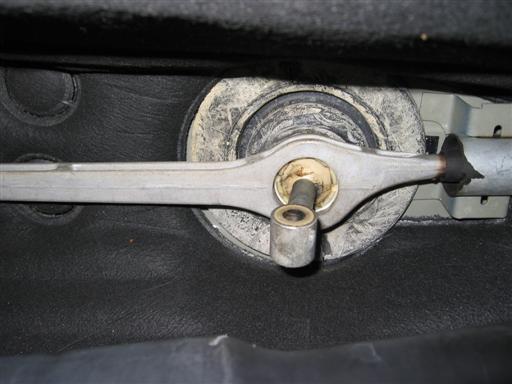
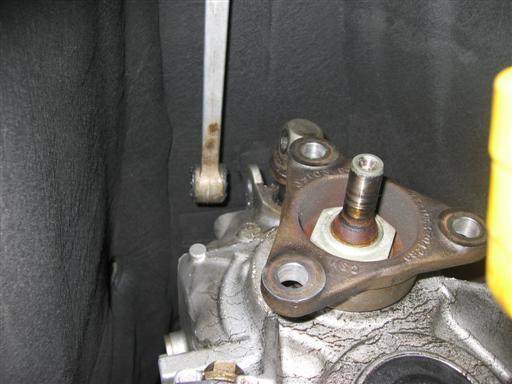
Step 5: Disconnect drive shaft and remove guibo.
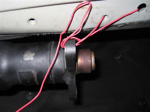
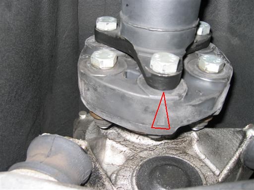
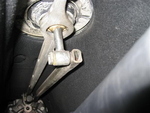
You will want to have the parking brake disengaged for this, as you will need to be able to turn the drive shaft to access all the nuts and bolts. The guibo bolts and nuts are 18mm and are torqued at around 75 ft-lbs, so long wrenches will help. Remove the 6 nuts and bolts. When they are removed, you will be able to slide the drive shaft back about and inch. The spline that the shaft slides back on is shown below. You will need to wiggle the drive shaft and guibo around to pull the guibo free. Once free, secure the driveshaft out of the way with some stiff wire. I used a couple mounting holes in the undercarriage.
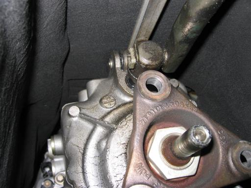
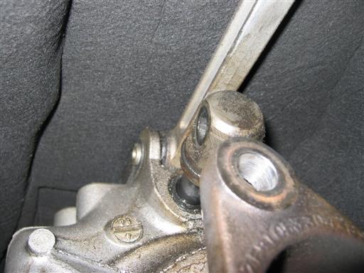
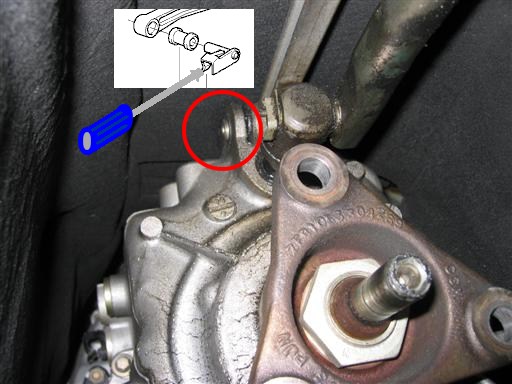
Step 6: Disconnect shifter selector rod.
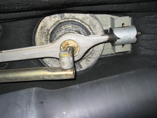
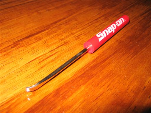
The shifter selector rod connects to both the shifter and the transmission via pins. These pins are held in place with c-clips, as shown below. The c-clips are a bear to get out, but are a little easier with the right tool. I bent up a small screwdriver to give me a little lip I could hook onto the clip and pull it off with. You can also use an offset screwdriver. Just pull the clips off and the pins will slide out with a little wiggling. Each pin has a pair of thing, yellow, washers that go on either side of it. Be sure to keep track of those for reassembly. Also, take note of the position of the selector rod and the location of the bend in it. The rod should go along the passenger side and the bend should be nearest the transmission. It is possible to put the rod back in wrong, and it will cause problems.
Step 7: Lower rear of transmission.
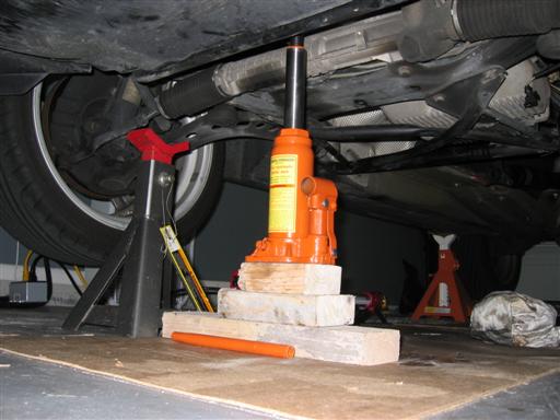
You are now ready to lower the transmission slightly. This will give you easier access to the bell housing bolts, slave cylinder, and backup switch. I found that a bottle jack was very convenient for this. Place the jack under the transmission. There is a nice spot for this just in front of the drain plug. Jack up the transmission JUST enough to take the tension off the transmission mounts.
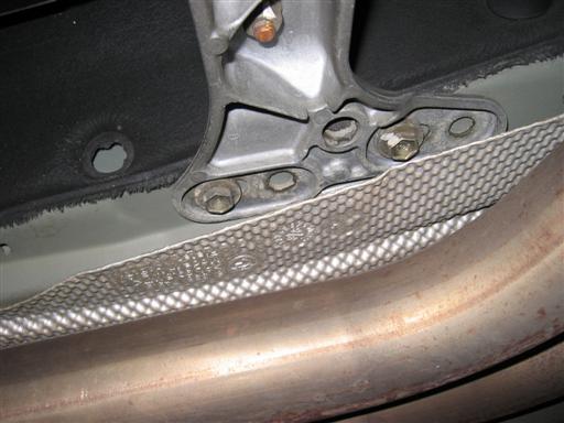
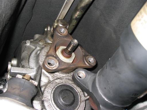
Unbolt the transmission mounts from the cross brace. These are 13mm nuts with fairly low torque. With the mounts disconnected, remove the 4 bolts holding the cross brace to the body. These are also 13mm bolts, but torqued higher. You should now be able to remove the cross brace entirely. You can choose to leave the mounts attached to the transmission or remove them. It makes no difference.
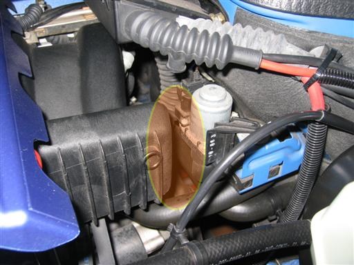
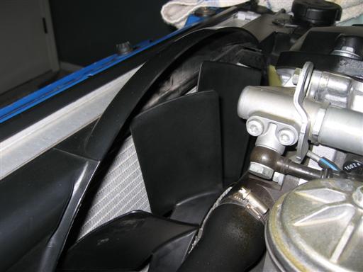
With the mounts and cross brace removed, you may now lower the transmission slightly. This is a good place to have someone watching the motor from above. As the transmission lowers, the engine tilts back as well. If you tilt the engine back too far, the intake manifold will hit the heater valve behind it, highlighted below. Lower the transmission as far as you can without letting the intake manifold contact the heater valve.
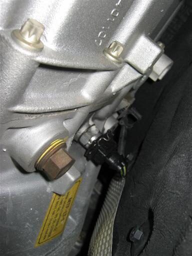
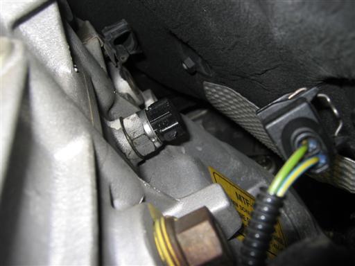
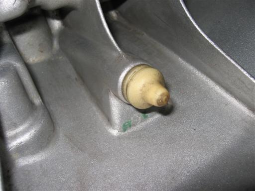
Step 8: Disconnect backup switch.
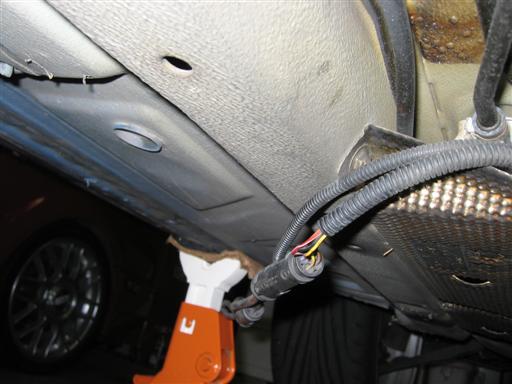
Remove the backup light connector, located on the passenger-side of the transmission. You can do this by pulling the silver, metal, retaining clip out of the connector with some needle-nose pliers. The connector will then just slip off the switch. Be sure to snap the retaining clip back into the connector after removing it. The harness for the backup switch goes over top of the transmission and is held by two plastics clips. Slide the harness out of the clips and over the transmission. Tie the harness out of the way somewhere on the driver-side.
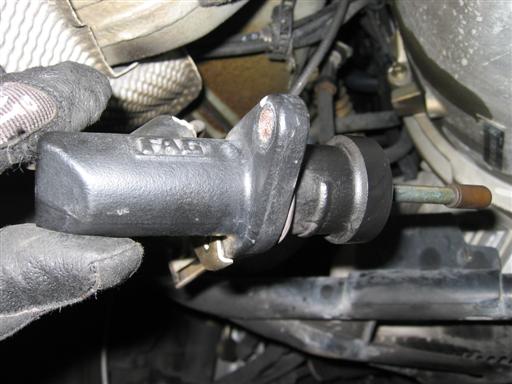
Step 9: Remove clutch slave.
The clutch slave cylinder is held to the transmission by two nuts. The clutch slave is also under a small amount of tension because of the hydraulic system. A long extension will give you easy access to both nuts and allow you enough room to turn a ratchet. Tie the slave cylinder up some place out of the way with some stiff wire.
WARNING: Do not press the clutch pedal FOR ANY REASON with the slave cylinder removed from the transmission. This will explode the cylinder and make quite a mess under the car.
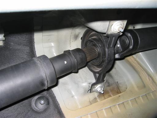
Step 10: Disconnect shifter carrier rod.
Next up is removing the shifter carrier rod from the transmission. It is held to the top of the transmission by a pin with a retaining clip built into it. The pin/clip is shown in the first picture. It is a real pain to remove, but it can be done by sliding a large (not huge) slotted screwdriver into the back of the clip, and forcing it upwards. This is easier said than done, because of clearance aboce the transmission. You will get a good idea of how it works when you get your hand on it. Just flip the clip up (vertical), and slide the pin out on the driver-side. The carrier rod will now be free of the transmission. You can leave the carrier rod connected to the shifter and carrier bearing in the rear, as it will be largely out of the way for the rest of the operation.
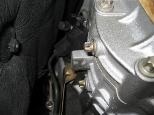
Step 11: Remove bell housing bolts.
Ensure that both the transmission and the front of the engine are well-supported. When the transmission comes off, the motor will be front-heavy and will rock forward.
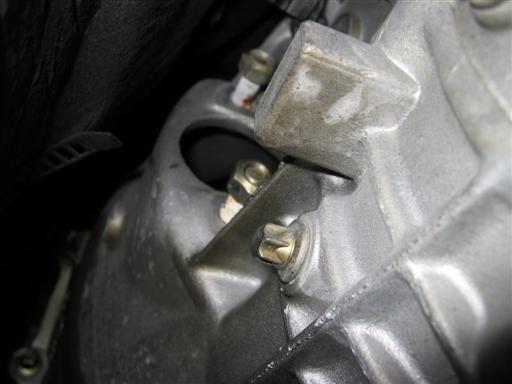
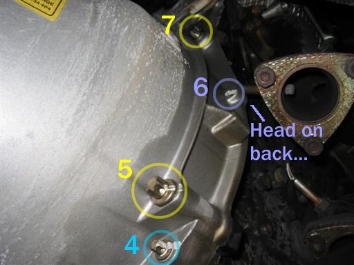
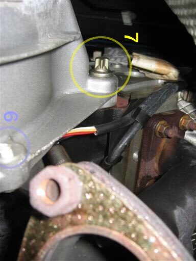
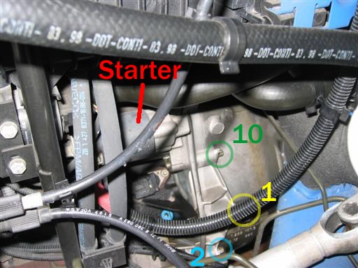
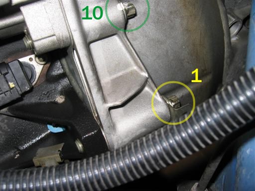
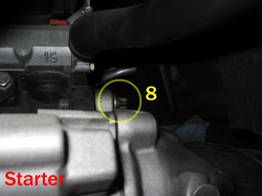
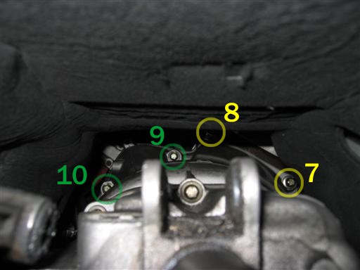
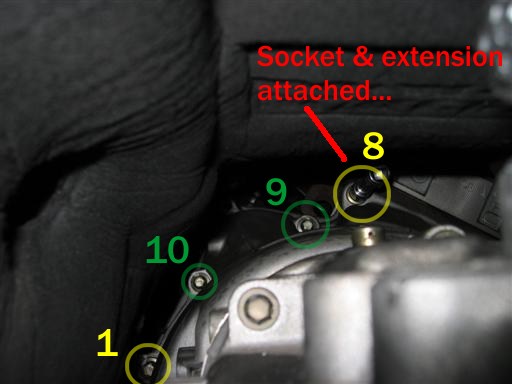
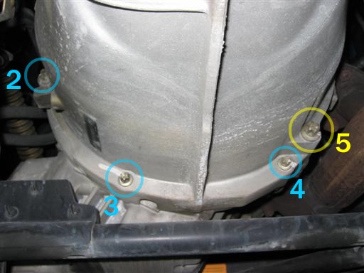
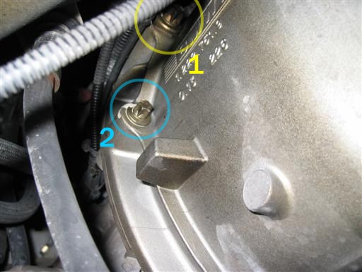
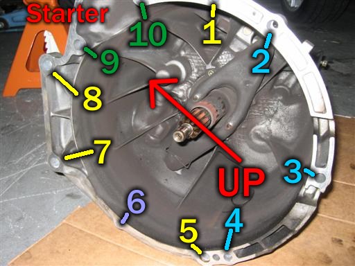
Now remove the bell housing bolts. There are 10 total. 4 large E14 (2 short, 2 long), 2 medium-sized E12 (holding the starter), 3 small E11, and 1 tiny 10mm hex. You can remove these in any order that suits you, since the transmission and engine are being supported by jacks, and the transmission is not going to come off on its own. I chose to remove the bolts in order of size, starting with the small ones. I left the #5 bolt in for last, as it was easily accessible. Make sure to take note of where these bolts came from as you remove them, in case yours differ from my drawing. They will only go back in correctly in one place, however.
You will need long extensions for many of these bolts, though I didn’t find any to be too hard to get at. The #8 bolt is a bit tricky, but I was able to get it using several straight extensions and a short wobble extension. I only needed the wobble extension because I needed an extra degree or two of angle on the extension to get the socket fully seated. I highly recommend using 1/2″ drive extensions where possible. They will flex less as you torque on them, and since you will be using long extensions, this will be very noticeable. An extra set of hands to align the sockets from the engine bay is extremely helpful here.
If you get stuck fighting a bolt, take a break, spray it down with some more Blaster, and go back at it in 20 minutes. Fighting corroded bolts is a good way to hurt yourself or break a bolt.
The colors in the photos below indicate to the size of the bolt. Yellow is E14, green is E12, blue is E11, and purple is 10mm hex.
Step 12: Remove transmission.
Double-check that the engine and transmission are supported. If you are using a transmission jack, it should already be in place and supporting the transmission. I didn’t use one. Also make sure to support the front of the engine. When the transmission is removed, it will be unbalanced and rock forward. When it does that, the radiator fan will come into contact with the radiator. It may not cause damage, but those are two components that I didn’t want to have to replace because of a mistake.
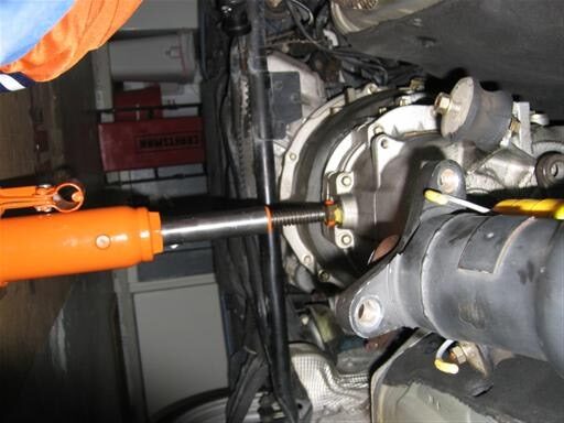
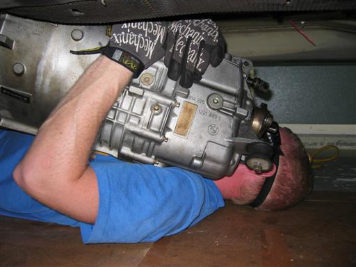
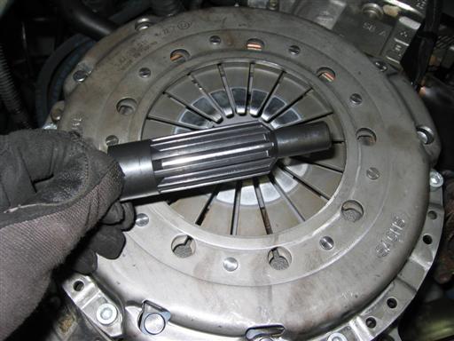
With all the bell housing bolts removed, the transmission is ready to come out. Mine was stuck to the block, however. I gave the edges of the bell housing a good spray of Blaster and let it sit for a bit. I then placed a small bottle jack (shown in several photos) between the edge of the bell housing (near bolt #6) and the front cross member. I then extended the jack slowly until it began pushing the transmission away from the block. Once I had a small gap around the bell housing, I was ready to go. I didn’t have a transmission jack, only had a crummy floor jack. I found that it just got in the way when wiggling it free. So… I lowered it by hand, as shown below. I don’t recommend this for everyone, since the transmission is around 75 pounds and has many protrusions to injure you with. The rear of the transmission will need to be angled down to clear the transmission tunnel after the input shaft is removed from the clutch/pressure plate assembly. Be very careful not to let the weight of the transmission hang on the input shaft at any time. This can ruin bearings in the transmission, as well as the pilot bearing in the crank.
Lower the transmission and slide it out from under the car. Be careful not to drop it. There are plenty of parts that seem like a good smack might cause some cracking.
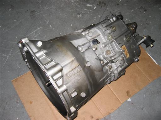
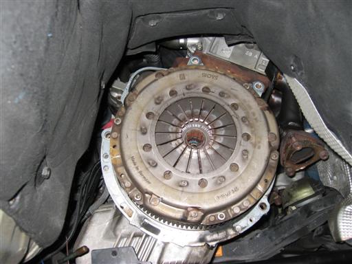
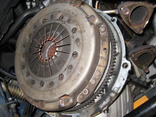
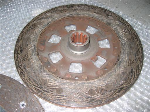
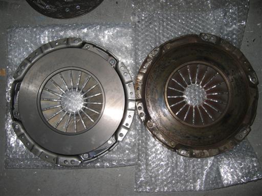
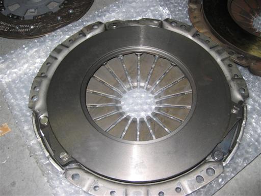
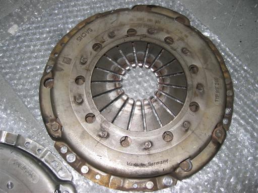
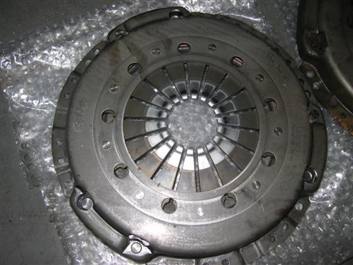
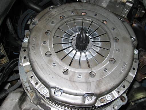
Step 13: Remove pressure plate and clutch disc.
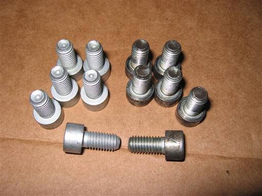
Remove the 6 6mm hex bolts around the perimeter of the pressure plate. The plate is held on with a friction fit from 3 posts that pass through the pressure plate from the flywheel, so it will not fall off on you.
I get the pressure plate off, I carefully pried it away from the flywheel with a long, slotted screwdriver. Do this a little bit at a time and work around the pressure plate evenly. Now is a good time to insert your clutch alignment tool into the clutch disk. If you don’t, the clutch disk will fall out when you pull the pressure plate free. You would also be wise to wear a dust mask and goggles, if you aren’t already. There is plenty of clutch material sitting inside the pressure plate waiting to fall out on you. There is often asbestos in the clutch material, so you don’t want that in your lungs.
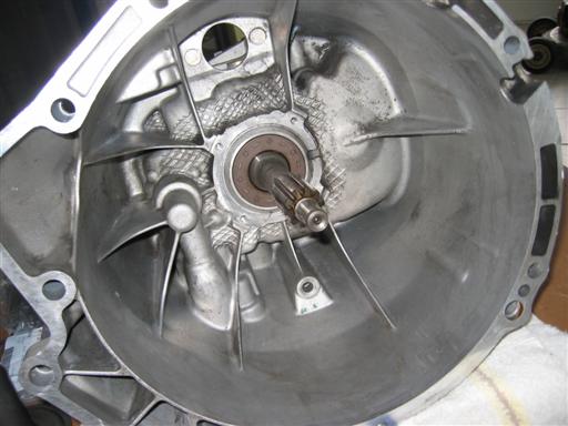
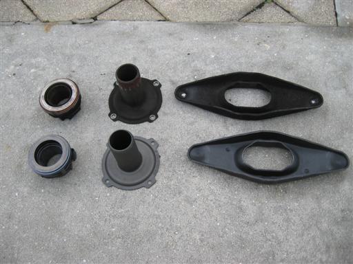
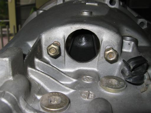
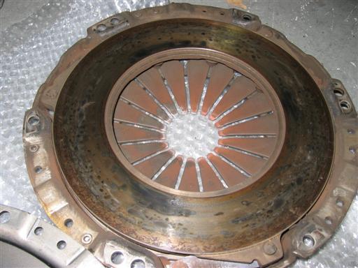
Step 14: Remove bell housing internals.
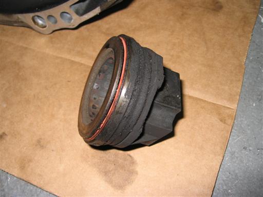
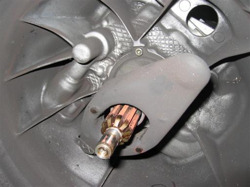
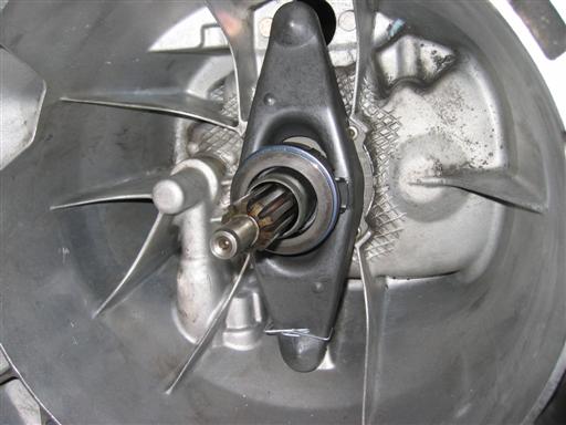
The clutch bearing will slide right off the input shaft of the transmission, if it didn’t already fall out during the transmission removal. The clutch fork is held in place by a spring clip, which attaches itself to a pivot ball. The pivot ball itself is just friction-fit into a hole in the transmission casting.
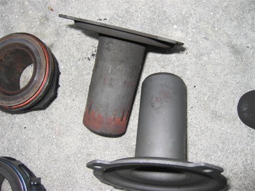
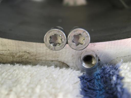
With the bearing and fork removed, you will now need to remove the bearing guide tube. This is the tube that the throw-out bearing slides on and goes around the input shaft. As you can see, mine had some obvious wear. The tube is held in place by 4 5mm hex bolts.
Step 15: Clean transmission.
This step isn’t terribly necessary, but I couldn’t bring myself to put the transmission back on without cleaning all that clutch material out of it. Brake cleaner and some rags will work wonders.
Step 16: Lube new parts.
You want to be very frugal with the amount of grease you use anywhere in the bell housing. Just a very light film is sufficient. Using too much can result in grease being slung around in the transmission, gather clutch material (causing wear), or get onto the clutch itself. All of those are to be avoided.
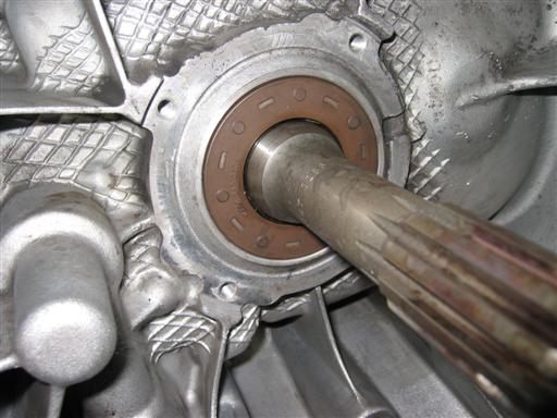
Apply a very light film of graase to the input shaft and splines, as well as the outside of the bearing guide tube, the tip of the pivot ball, and the contact points on the clutch fork. The wear points on the fork will be clear in the next step.
Step 17: Install bell housing internals.
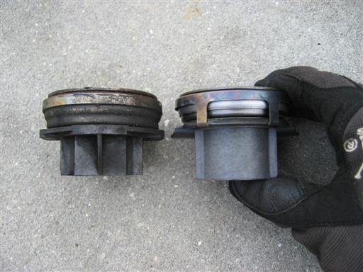
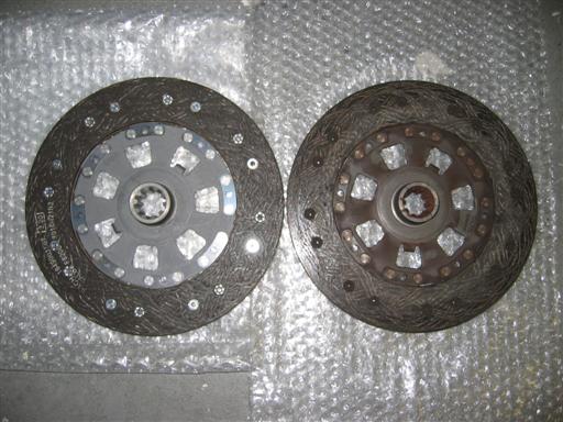
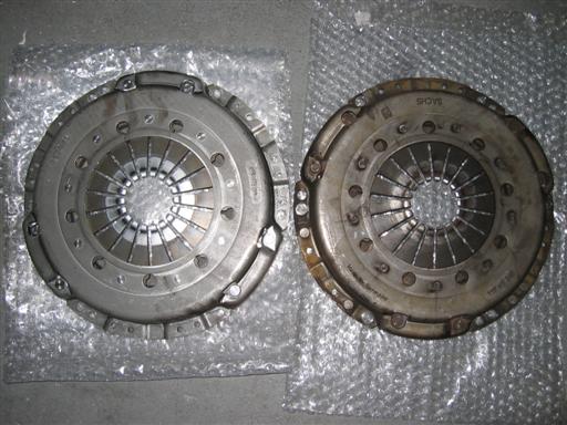
You can see the comparison between the new and original parts in the pictures below. The wear on the clutch fork and bearing guide tube is apparent. You can also see the shiny spots on the clutch fork. These are the positions where you could be placing a thin film of grease. Begin reassembly by placing the pivot ball back into its hole.
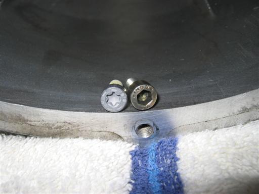
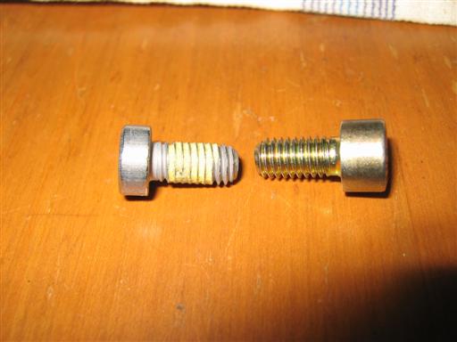
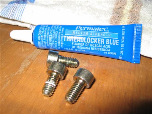
You will notice that certain new parts do not match their original counterparts. The throw-out bearing is an OEM Sachs piece, as is the original. The difference did not affect function in the least. You will also notice that the bearing guide tube bolts are different. Both the original and the replacements are BMW parts with the same part number. They must have switched to the torx head bolts at some point. The torx-head replacements were very shallow and stripped easily (shown below). I couldn’t bring myself to leave those little nightmares in the bell housing for the “next guy”, so I re-used the original hex bolts. Since the replacements came with an application of some yellow thread locker, I applied a dab of Permatex blue thread locker on each of the originals when I reinstalled them.
With the guide tube installed, install the clutch fork. The clutch fork is the same on both ends, so it doesn’t matter which end goes on the pivot ball. Be sure the clip the fork to the pivot ball with the spring clip.
You can now slide the throw-out bearing onto the bearing guide tube. Make sure the two tabs on the bearing line up with the contact points on the clutch fork.
You can see the fully-assembled unit below, as well as the spot of grease on the back of the clutch fork through the slave cylinder hole.
Editor’s note: Now is a perfect time to replace your original nylon pivot pin with a brass retrofit. The brass version will not distort or smash like the OEM nylon pins can and often do. Brass pivot pins will also keep your shifts much cleaner and precise.
~M. Oswald
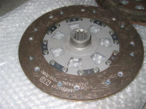
Step 18: Install clutch disc and pressure plate.
Step 19: Install transmission.
Ensure that the starter is out of the way of the bell housing before you begin lifting the transmission. Also, ensure that the metal gasket surrounding where the bell housing will meet the block is clean of debris and properly aligned.
Lift the transmission back into place with a jack or by hand (like I did). Take care to insert the transmission into the clutch assembly as level as you can to help with installation. Once the input shaft is sliding into the clutch assembly, push the transmission forward and up against the block. Like during removal, take care not to ever let the weight of the transmission rest on the input shaft. If you get tired while lifting the transmission into position, remove it entirely before taking a rest. There are two locating “dowels” around the bell housing. Ensure that these are lined up, or the bell housing will never mate up to the block. Once the dowels are aligned, the transmission can be pushed tightly against the block.
Support the transmission with a jack and immediately move onto the next step.
Step 20: Install bell housing bolts.
While supporting the transmission, immediately begin installing the bell housing bolts, starting with the large E14 bolts. Once the E14 bolts are on and snug, install the small E11 bolts. Torque the E14 and E11 bolts in a star pattern (as close as you can). Once again, a second set of hands makes this task a lot easier by starting bolts and seating sockets from the engine bay.
Now, install the starter using the two medium-sized E12 bolts and torque them to spec. Install the tiny 10mm hex bolt on the passenger side last. The hex bolt has a very small torque spec, so be careful not to strip it.
Step 21: Connect shifter carrier rod.
Lube the carrier rod bushing liberally and attach it to the transmission with the pin/clip.
Step 22: Install clutch slave.
Reinstall the clutch slave cylinder by carefully aligning the pin so it seats itself in the indent in the clutch fork. As you can see in the photo below, it a pretty big target to hit, so you should be ok as long as you insert the cylinder into the housing straight.
You should have a bit of pressure fighting you when pressing the slave cylinder forward onto the threaded studs. If you don’t, you are not aligned correctly. If you don’t think you have the pin seated correctly, pull it out and do it again. Be certain.
Hold the slave in place with one hand and get the nuts started on the threaded rods with the other. This is easier said than done in the transmission tunnel, but is made much easier by the transmission still being lowered slightly. Torque the two nuts to spec.
Now, you need to test your clutch pedal to make sure it is seated correctly. Slowly, and gently, press the clutch pedal to the floor. If at any time the clutch doesn’t feel right, stop and re-check the slave cylinder. If it isn’t aligned correctly, it will not be pressing on the clutch fork and will likely burst the seal on the cylinder and drop the pin into the bell housing. You do not want this to happen.
Step 23: Connect backup switch.
Route the backup switch back over top of the transmission and into the two plastic clips. Plug the connector into the switch.
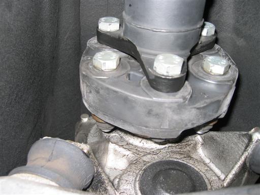
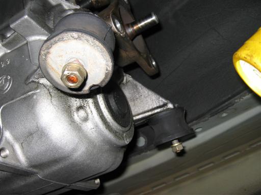
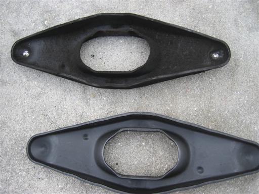
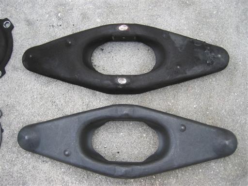
Step 24: Bolt up transmission mount.
Jack the transmission back into place, making certain that any engine jacks have been removed. Re-install the transmission mounts, if you removed them, but do not torque the nuts on them. Attach the transmission brace to the transmission mounts and, again, do not torque the nuts. Bolt the transmission brace to the body with the 4 13mm bolts and torque them to spec. The transmission mounts should already be in place between the transmission and transmission brace. Ensure that they are aligned with the nubs on the brace. Next, lower the transmission until it is resting entirely on the transmission mounts. Now torque the transmission mount nuts to spec. Do not over-tighten the nuts on either side of the transmission mounts, or you will get a lot of vibration when driving.
Step 25: Install shifter selector rod.
Lube the connecting points for the shifter selector liberally on both ends. This is also a good time to lube the shifter where it pivots in the carrier rod. Install the shifter selector on the passenger side of the car, with the bend closest to the transmission. If the selector rod is installed incorrectly, it will contact the guibo when the driveshaft spins. Be sure that there is a yellow washer on both sides of the connecting points, and slide on the c-clip.
Step 26: Install guibo and attach drive shaft.
Clean and re-grease the center sleeve on the driveshaft. Re-install the guibo and attach the driveshaft using the 6 nuts on bolts. The nuts are one-time use, so use new ones. Ensure that the arrows on the edge of the guibo are pointing towards a flange. Install the bolts and torque to spec in a star fashion.
Step 27: Install exhaust heat shields.
Re-install the two exhaust heat shields. First the rear, then the passenger-side. You can use a socket to tighten the washer-nuts that hold the shields in place, but use a light touch. The nuts look like they would deform/strip very easily.
Step 28: Install exhaust center pipes.
Slide the exhaust center pipes under the car and attach the O2 sensors. Be careful not to torque them down too much. Hoist the pipes into position and slide the front of the pipes over the front x-brace. This will give you a good place to rest the front of the pipes while attaching the rear mufflers. Use a jack to support the rear of the center pipes. Attach the rear mufflers, making sure to put the gasket rings in place before bolting the mufflers on. You will need 12mm and 13mm combination wrenches for this part. Interestingly, the BMW replacement nuts for these were copper, while my original nuts were steel. Yet another design change, I guess.
Once the rear mufflers are bolted on, you can begin routing the wires for the O2 sensors. Pass them over top of the pipes, towards the driver side, making sure to clip them to the heat shield where applicable. Re-connect the sensors to the main harness and clip the round connectors to the heat shield.
Now move up to the front of the car to attach the front of the pipes to the headers. Be sure to replace the copper gaskets here, as they are one-time use. Wiggle the pipes into position and get a nut or two started. I found this to be much more awkward than removing them. Once you get all 6 nuts on, torque them to spec.
Step 29: Lower car.
Carefully lower the car off the jack stands.