Article by: Vinci
Article applies to: all e36 Z3 roadster models.
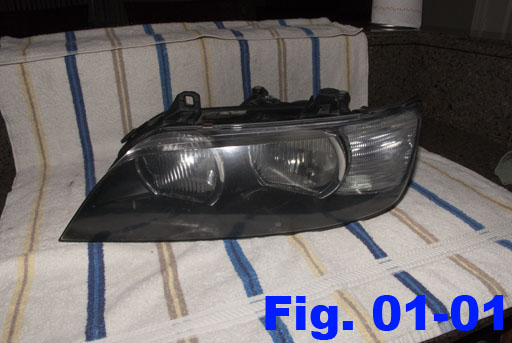
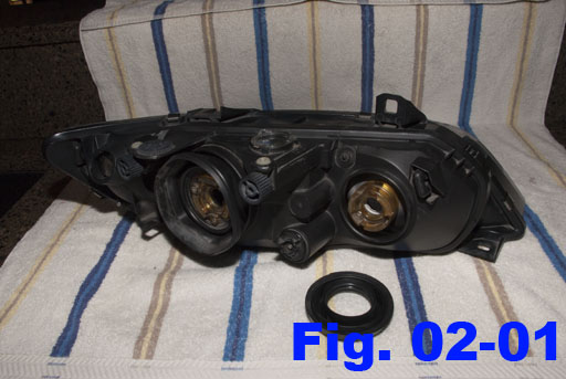
This guide covers the process of opening and disassembling the Z3 headlight assemblies. All Z3 models and years come with the same overall headlight assemblies, with minor internal differences. This guide applies to all variations.
Please note that this guide covers the steps required to service a component that was never designed to be serviced. Every step below should be performed with great care. By now, the Z3 headlights that you are likely to work on will be 10-15 years old. The plastic will be brittle and easy to damage. The specific headlight assemblies pictured in this guide show existing damage. Please compare your lights to the photos carefully so that you can take any differences into account and avoid such damage.
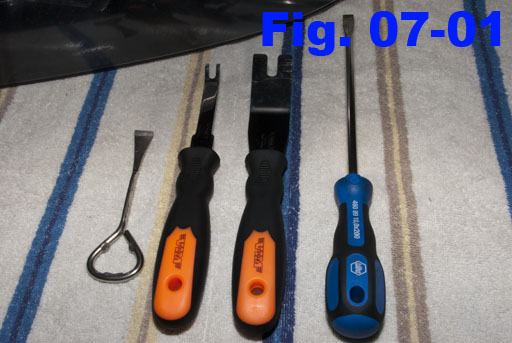
Tools/parts:
- Oven or heat gun
- Phillips #2 screwdriver
- Various prying tools
Step 1: Clean the lights.
Headlight housings tend to collect a lot of dirt and grime while in service, and these are things that you will not want to have on your hands and getting inside the housings while working on them. Because of this, it’s a good idea to give the housings a thorough cleaning with a damp cloth. Do not submerge the housing or douse it heavily. Avoid cleaning chemicals other than mild dish soap, if needed at all.

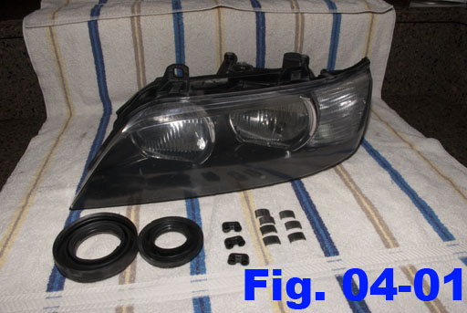
Step 2: Remove the rear seals.
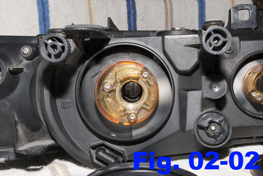
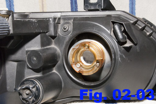
The back of each reflector bucket is surrounded by a gap in the outer housing, to allow for aiming. This gap is sealed by a large rubber seal. These seals are just held in place by some small lips on both the amber-colored bulb holders and the surrounding black headlight housing. Carefully lift the ledges and pull the seals away. These can then be cleaned with more soap and water, if needed.
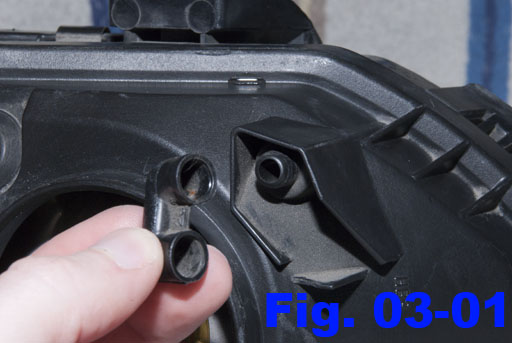
Step 3: Remove the housing vents.
The headlight housings are equipped with 3 vents to help keep moisture from collecting inside. These vents are friction-fit into place and can be removed easily with a little wiggling.
Step 4: Remove the metal lens clips.
There are seven metal clips around the perimeter of the lens. These clips are simply snapped into place and offer a secondary means of holing the lens and headlight housing together. For what it’s worth, they probably aren’t necessary when the lens is properly glued into place. It’s worth noting that these clips are stainless and shine up nicely with a little metal polish.
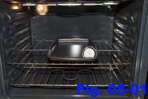
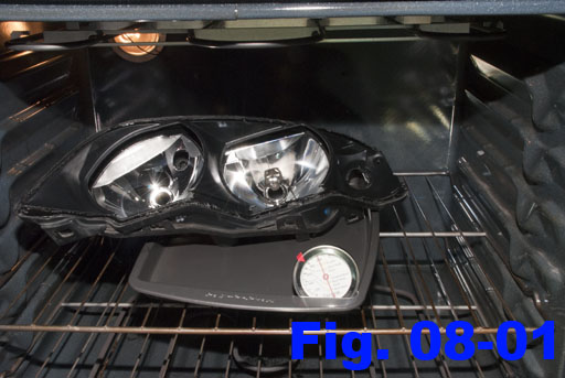
Step 5: Prepare the oven.
In a standard kitchen oven, rearrange your wire racks to allow the headlight to sit as close to the center of the oven as possible.
Heat the oven to around 225 degrees (Fahrenheit). Allow the oven to completely “preheat” and settle to a constant temperature. Ovens will vary wildly from model to model, especially with age, so always confirm the actual internal temperature with an oven-safe thermometer.
I suggest using a clean baking sheet to keep the headlight housing from sitting directly on the rack.
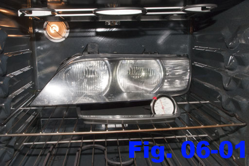
Step 6: Bake the housing.
Place the headlight housing onto your baking tray and ensure that no part of the housing is touching any part of the oven itself. Allow the headlight to bake for 10-15 minutes uninterrupted. This will help to thoroughly soften the glue that seals everything together.
Bake the headlight housings one at a time. The housing and glue will cool quickly, so trying to do two at once will almost certainly leave the second housing too cool to work on by the time you get to it.
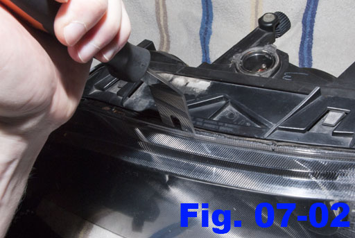
Step 7: Remove the front cover.
Step 8: Re-bake the housing.
Place the housing back into the oven for another 15 minutes. Separating this seal will be more difficult than the lens, so I suggest that slightly longer bake time to help give you some more work time.
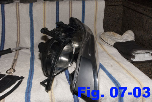
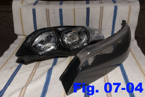
Step 9: Remove the rear cover.
In addition to sealant, the rear cover is also held in place with 5 “clips” that are built into both sides of the housing. These clips are not easy to operate and will require some very cautious use of some thin prying tools to work the clip loose while also separating the seal. I found that separating the seal just enough to keep the barb of a released clip unhooked allows you to move onto the next clip and do the same thing without pulling the seal apart so much that the remaining clips get bound up and have a hard time releasing.

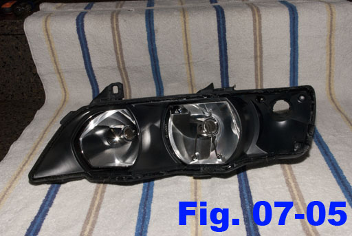
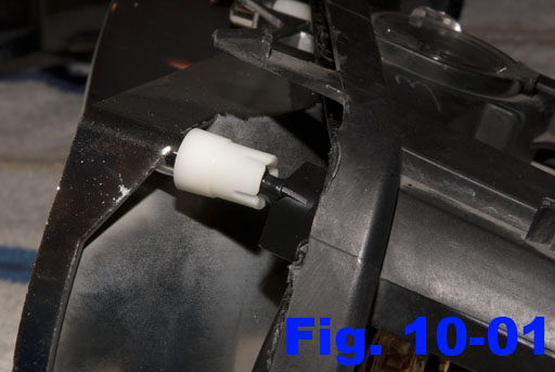
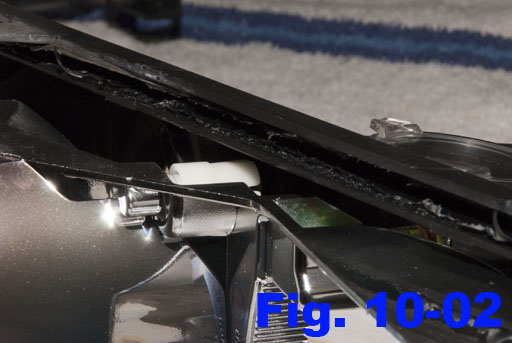
Step 10: Remove the reflector assembly.
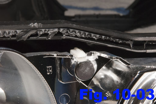
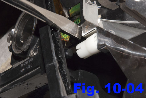
Removing the reflector assembly is simply a matter of releasing it from the aiming mechanism. There is a ball-in-socket connection point on the upper-outside corner of the housing (figure 10-01) and another one at the top-center (figure 10-02). There is also a different style of ball-in-socket connection at the bottom-center of the housing (figure 10-03).
To release the first two connections, simply insert a prying tool between the outer housing and the reflector assembly, next to the socket. Pry very carefully until the ball pops out of the socket (figure 10-04).
The third connection cannot be released like the previous two. To release this connection, insert a prying tool under the outer clip and raise it while prying between the outer housing and the reflector assembly (figure 10-05). Once pried free, the ball-in-socket connection looks like figure 10-06.
Step 11: Reassembly.
Reassembly is the reverse of disassembly.
When resealing the outer housing, prepare your oven again like in Step #5 and reheat the pieces like in Step #6.