Article by: cnn
Article applies to: all e39 models.
I just did my entire front suspension overhaul and here is the DIY. It is a long write-up, so get some Popcorn and Coke to get through it!
At 105K miles, here is my observation:
- The Thrust Arm: Bushings are long gone (may have been gone around 50K) with oil leaking out, rubber cracked; the ball joint side is a bit loose but no play yet.
- The Control Arm: Bushings are still OK, the ball joint side is a bit loose but no play yet. May have another 30-40K miles.
- Tie rods: INNER and OUTER ball joint is a bit loose but no play yet. May have another 30-40K miles.OEM Struts (Sachs) are long gone with no resistance and oil leaking out the top seal.
- The Strut Guide (with built-in bearing): grease dried out, there is slight-moderate play in it. May have another 30-40K miles.
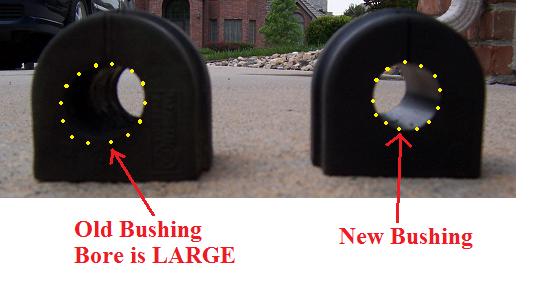
- The Sway Bar Rubber bushings: the hole is widened and loose.
Now with brand new suspension, the car is nice and tight. I will have to wait to do the Rear Suspension later (No time right now with family and kids).
SPECIAL TOOLS AND NOTES:
1. The 13/16″ (= 21mm) Spark Plug Socket, plus Metric Allen Wrenches for counter-holding the bolts:
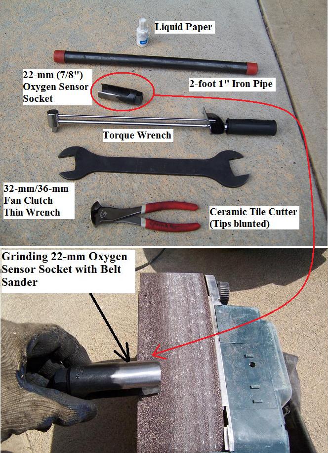
2. One 2-foot length of black cast iron piping $5 at Home Depot Hardware Store. This helps with the 3/8″ ratchet to undo tough nuts/bolts.
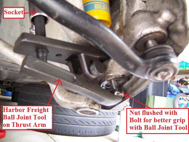
3. Harbor Freight Ball Joint Removal Tool: PN 99849 ($18.00): http://www.harborfreight.com/cpi/cta…emnumber=99849
- This is a MUST! Don’t even dream doing this job without this Ball Joint Removal Tool!
- Remember to spray WD-40 (or similar lubricant) onto the Ball Joints and let it sit for 30 minutes before removing it.
- Oil/Grease the ball joint tool a bit before using it. At this stage, you can dream about Bahamas vacation when tightening the BJ Tool (22-mm socket-ratchet with iron pipe) but you will hear a “Rude Awakening” when the ball joint comes loose: a loud bang like a shotgun!
- Ear plugs are very useful when you get to this stage!
* The trick: Tighten in increments, let’s say 4-5 moves at a time to allow the ball joint to adjust to the force; stop and repeat in a few minutes. By the time you reach 110-120 Nm, you should get the loud bang! The ball joint Tool will drop to the ground.
4. Strut Nut Socket.
- The stock Sachs strut nut is 21 mm and the 13/16″ (= 21mm) Spark Plug Socket works just fine.
- The Bilstein strut nut is 22 mm, so you have a few options:
a. From Speaking with local mechanics, they laughed at me when I mentioned I need 22 mm Socket with Hex Sides at the top for a wrench to fit. They all use Impact Air Tool set at the lowest setting to get about 60 Nm. They have done hundreds of shocks without problems.
b. Re-use the Stock Sachs 21mm Nut (it will fit the Bilstein), probably OK to re-use 21-mm stock Nut.
c. The special 22-mm Socket with a Hex Top (Like a spark plug socket) is expensive and difficult to find. What I did was: Get the Harbor Freight Oxygen Sensor Socket Tool: PN 95045 ($4.00):
http://www.harborfreight.com/cpi/cta…emnumber=95045
The Oxygen Sensor Socket Tool is a bit “fat” and cannot be inserted into the Strut Guide to tighten the nut, just grind the socket a bit and you will be able to insert it.
I used a Belt Sander turn upside down and grind it down a bit. You can also use a Stone Wheel Bench Grinder as well. I made a nice tool for Bilstein Strut 22-mm Nut for only $4.00!
5. Liquid Paper: You wonder why right? Yes, use this (or any paint touchup brush) because there are many nuts/bolts and it is easy to forget which one has been torqued or not. At BMW factory, they use blue paint to mark a nut or bolt that has been properly torqued, so later at a glance they know the bolts/nuts have been torqued.
6. Wrenches: Get a complete set of metric anyway to qualify you as a Saturday mechanic. . . . . : )
Most Metric Wrench Set jumps here and there, missing one or 2 wrench sizes. Get a compete set, i.e. every single size from 8-mm all the way to 25-mm for your collection!
- LONG 13-mm. The 13-mm wrench is for the Sway Bar Bushing nut, which is in a very tight place on the passenger’s side and you DO need a long wrench for extra leverage!
- You need a total of two (2) 18-mm wrench for the Thrust Arms. The additional 18-mm wrench is for the Thrust Arm, which is in a VERY TIGHT space (i.e., no space for socket); unless you remove the Plastic Housing next to it.
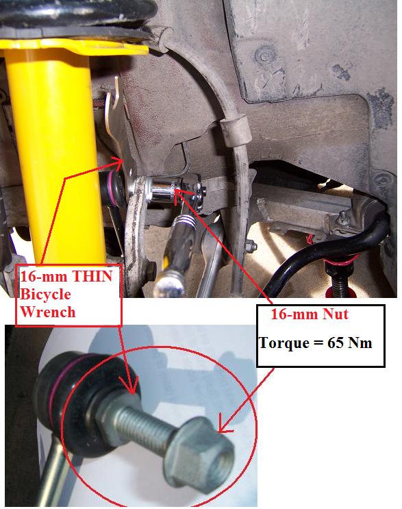
- A 16-mm thin bicycle wrench is very useful to hold the Sway Bar Endlink bolt while you undo the 16-mm nut. The standard 16-mm wrench is a bit ‘fat’ and can damage the end link Rubber boot: don’t ask me why but I made this mistake in my 1998 Volvo V70, the 16-mm wrench pushed the boot too far out, I spent 45 minutes repairing the rubber boot = not funny!
- If you use a standard 16-mm wrench, then BE VERY CAREFUL not to damage the rubber boot! The 16-mm BICYCLE wrench makes this a breeze! It is $4-5 at local bicycle store, I use ‘Park Tool’ wrench (This is known as a ‘CONE Wrench’ in the bicycle world): http://www.parktool.com/products/
7. The BIG Trick: Jack up BOTH Sides but work only on ONE Side at a time. Why? Because if you jack up only one side of the car and try to remove the end link from the sway bar, you will likely use the 4-letter word! Jacking up both sides makes the job MUCH easier.
Why work only one side at a time? Because you want to leave the other side alone as a reference in case you want to know how nuts/bolts are fitted, orientation etc.
8. From the Start, Undo all the nuts/bolts on both sides but STOP as soon as the nuts are flushed with the end of the bolts, Why? This loosens all the nuts but keep the components (tie rods, thrust arms, control arms) in place. Also this allows space for spraying lubricants such as WD-40 into the Ball Joints. For Ball Joints Nuts: if you leave the nut flushed with the end of the Bolts, you now have extra place for the Ball Joint Tool to bite, and less likely to slip out (see pic later)!
9. Do this inside of your garage or out of place in case you don’t finish the job in one day, you don’t block traffic!
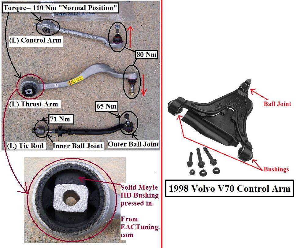
10. Note on BMW terminology: Go and look at let’s say a 1998 Volvo V70 with standard A-arm: 2 bushings and one ball joint. BMW simply splits this A-Arm into two (2) separate parts, each with its own bushing and ball joints and calls it “Thrust Arm (front part) and “Control Arm” (rear part). This split of the Ball Joints allows the Front Tires to move up and down in a more controlled manner (tires making more contact with the road under different situations) during turns —> spirited driving —> Ultimate Driving Machine!
11. Take special care not to damage any Rubber Boot. Nobody sells these Rubber Boots as separate items. If you damage any Rubber Boot, your only recourse is “Energy Suspension” brand aftermarket RUBBER BOOT part.
————-
PROCEDURES:
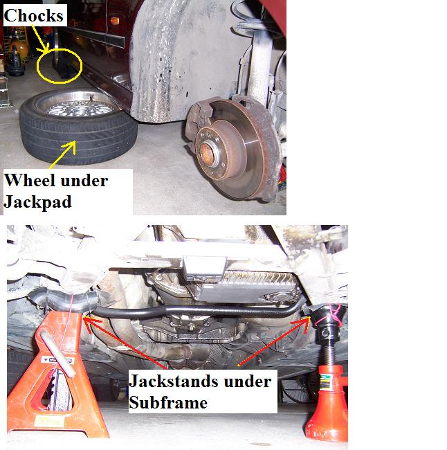
1. Raise and Support car on BOTH Sides but work on ONLY One Side at a time. Remove under car Plastic Shield. And support with jack stands as shown.
It is important to place jack stands at the proper spot so it does not interfere with removing nuts/bolts later. Chock REAR Wheel.
NOTE: I placed the tires under Front Jack Pad as 2nd line of defense in the extremely unlikely situation that the jack stand fails. Your life is worth more than the jack stand!
2. Get a container to store nuts/bolts because you can easily lose them. Make note of which nuts/bolts go where etc.
3. Use a Towel to protect paint work above wheel well! Removing the strut can damage paint work if not being careful!
4. Loosen all nuts and leave the nuts flushed with the end of the bolts, i.e. do not remove the nuts yet.
5. Now spray WD-40 on the Ball Joints (BJ) and let it penetrate the parts.
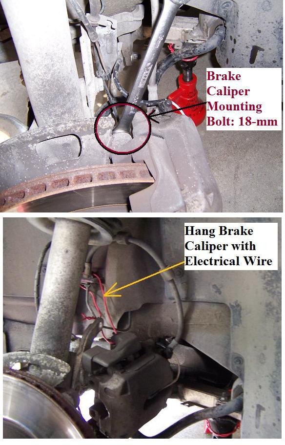
6. Remove Brake Caliper and hang it up using electrical wire:
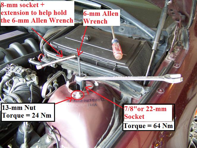
7. Loosen the Strut TOP nut (21-mm for Sachs and 22-mm for Bilstein) but do NOT remove it.
Use a 6-mm Allen Wrench to counter hold it (Trick: use an 8-mm socket and extension to hold the Allen wrench).
As mentioned above, 21-mm Nut —> Large Spark Plug Socket; 22-mm Nut —> Use the modified Oxygen Sensor Socket (sanded thin a bit):
8. Remove Sway Bar End Links:
9. Remove Outer Tie rod ball joint:
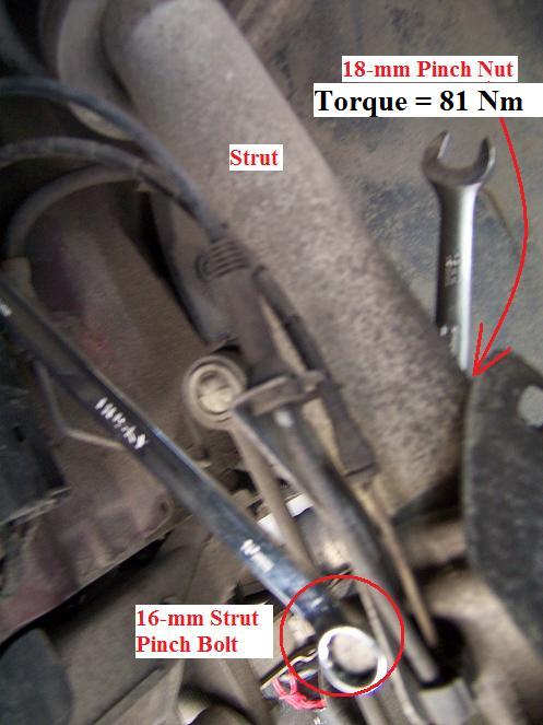
10. To remove Strut, remove the three (3) 13-mm nuts on the wheel housing. Steps #8-9 are necessary because the steering knuckle must be dropped to remove the Strut. Also Loosening the Thrust/Control Arms Nuts (on the sub-frame side) allows the strut to drop easier because it is not held by the bushing!). Spray some WD-40 at Strut-Steering Knuckle interface. Loosen the Pinch Bolt. Then twist the Strut back and forth to work it loose from the Steering Knuckle:
11. Place a jack below the Steering Knuckle and slowly lower it to allow the Strut to come out. The clearance is very tight, so watch to prevent paint work damage!
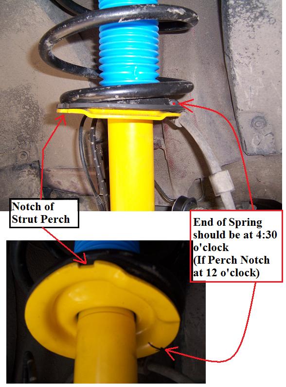
12. Now STOP and spend a minute to observe the Strut layout (if this is OEM and has not been changed previously). I think the Spring TOP and BOTTOM are different, so don’t mix it up.
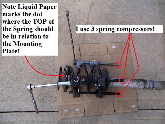
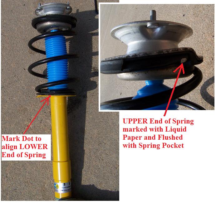
Mark the TOP of the Spring with Liquid Paper. The BOTTOM of the Spring is about 6 inches to the Right of the Notch on the Strut Perch or roughly at 4:30 o’clock if the Perch Notch is 12 o’clock.
* The Trick: use the old rubber pad as a guide, transfer it over to the New Strut and Mark the spot where the BOTTOM of the Spring should be, this will make your life mush easier and avoid the clunking problem seen in this forum from improper Strut installation. The Bottom line: follow the factory setup!
13. I use three (3) Spring Compressors instead of the usual 2 compressors, it is much easier (and SAFER) to compress the Spring this way.
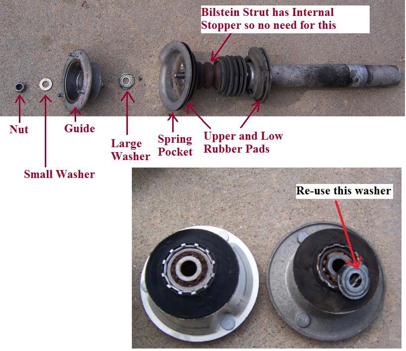
Remove the Strut and NOTE the layout. Do NOT lose any washers. Note that at the bottom of the Strut Guide, there is a protective washer, I re-use it. Of course, you can also get a new protective washer.
14. Now install the new Bilstein Strut, Rubber Pads (the UPPER Rubber Pad is different than the Lower Rubber Pad), New Strut Guide, Washers in the appropriate order. Align the Lower Rubber Pad with the Notch on the Strut Perch:
15. Hand-tighten the 22-mm TOP Nut for now, final torquing of this Nut will be done later in the car. Slowly release the 3 Spring Compressors making sure that the Spring lines up exactly as factory setup:
TOP of Spring touches the Guide notch and BOTTOM of Spring lines up with the 4:30 o’clock mark on the Perch.
16. NOW Stop! If you want to replace the Thrust Arm, do NOT install the Strut now! I made this mistake . . . Arghhh . . . and later have to undo the Strut-Steering Knuckle attachment because the Thrust Arm BJ cannot be removed with the Strut in place!
NOTE: Ball joint Removal Tool bites on both the nut (I leave it flushed with the bolt’s end) and the bolt:
17. Replace the Thrust Arm with new Thrust Arm, hand-tighten the 22-mm Nut but do not torque it yet (Do all of these Nuts later).
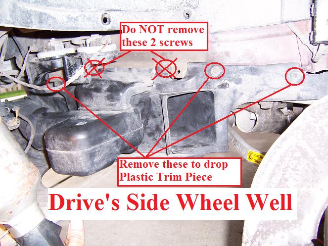
Before you can do this, you have to remove the Thrust Arm’s protective boot (10-mm bolts) and the Plastic Fender Lower Housing and the Plastic trim (8-mm socket) which itself has three (3) 8-mm screws:
18. Replace the Control Arm with new Control Arm, hand-tighten the 22-mm Nut but do not torque it yet (Do all of these Nuts later).
19. Re-install Strut, taking care not to damage paint work!
- Place a jack below Steering Knuckle and slowly raise it up.
- Twist the new Strut a bit to allow it to sit properly.
- Make sure the Strut bottoms down properly on the Steering Knuckle!
- Also check the R vs L marking lines up correctly as shown.
- Jack up the steering knuckle a bit more, verify that everything is correctly lined up.
- Now torque the Pinch Bolt to 81 Nm.
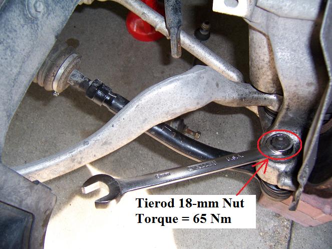
20. To replace the Tie rods:
- Stock ball joint Nut is 18-mm
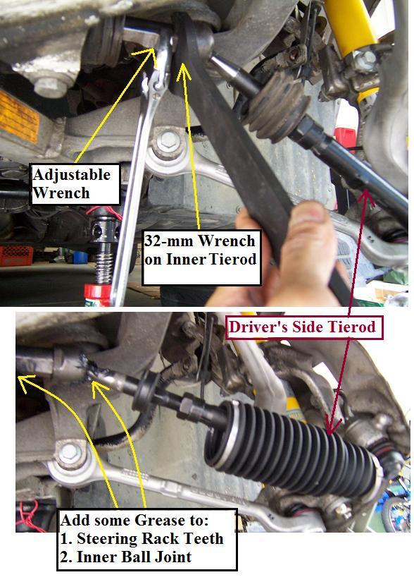
- Steering Rack Driver’s Side: 32-mm wrench and counter-hold with adjustable wrench.
* Do NOT forget to:
- Measure the old tie rod and set the NEW tie rod to same length before installation, this way you come close to previous setting, it makes subsequent alignment easier.
- Apply a bit of extra grease to the output shaft rack and INNER ball joints.
- Protect the Rubber boot.
- The Oetiker clamps: dry fit on the rubber boot first so you know what notch needed to tighten it. Use a Ceramic Tile Cutter (Tips filed blunted) or any Oetiker Clamp Tool to tighten it. Do not over do it. Just tighten it snug.
- The ball joint side: adjust the Steering Knuckle a bit here and there (support with jack) so the BJ can go in.
- Passenger’s side, no place to counterhold (simply a round Steering Rack Shaft: no place to apply the adjustable wrench), so apply 32-mm wrench and tighten it. I tighten it a bit below the published torque values (71 Nm) to avoid damage to steering rack. Actually when you remove the 32-mm nut, it was not tightened much from factory, it comes out easily. I made this mistake, so EDIT is below in red letters:
- EDIT Jan 14, 2009: The steering gear trick: The only place where you can apply the adjustable wrench on the steering gear (the part that slides R and L) is ON the driver’s side. So: undo the driver side but don’t install the tierod yet. Then do the pass’s side, using the square part on the driver’s side to hold it. Then do the driver’s side.
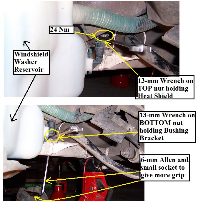
21. Sway Bar Bushings: 13-m wrench and Allen wrench to counter hold. Driver’s Side is easy.
Passenger’s Side 13-mm Nut will drive you Nuttttttttttts! The space is so tight to fit the 13-mm wrench. On the back side, there are two (2) nuts. The Top Nut holds the exhaust shield, which is lifted up a bit to work on the lower nut. Slide the Bracket out, rotate the Rubber Bushing upside down to slide it out. The Pass Side Bushing alone took me 1.5 h! It is a PITA. So, for The Pass Side Bushing, you are allowed to use the 4-letter word………….…………. : ) The alternative is to turn on some nice radio music to soothe your pain dealing with this nut!
22. Now go around the car and torque ALL nuts/bolts except for the nuts on Thrust Arm and Control Arm (which need to be torque with car on the ground and properly loaded (150lb in each front seat, rear center seat, full gas tank and some luggage and all that blah blah blah………….. 🙂
Many people simply torque these Nuts on Thrust Arm and Control Arm with car on the ground w/o the extra weights. Any nuts/bolts that have been torqued, mark with liquid paper or paint touch-up so you know. These include:
- Sway Bar end link 16-mm Nuts: 65 Nm
- Strut Suspension Tower 13-mm nuts: 24 Nm
- Strut Main 22-mm Nut: 64 Nm
- Thrust Arm Ball Joint 22-mm Nuts: 80 Nm
- Control Arm Ball Joint 22-mm Nuts: 80 Nm
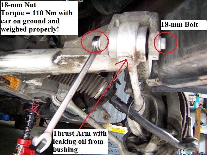
- Thrust Arm Subframe 18-mm Nuts: 110 Nm***
- Control Arm Subframe 18-mm Nuts: 110 Nm***
*** Torque these bolts ONLY with car on the ground and weighed properly (150 lbs each front seats, 150 lbs center rear seat, full gas tank…………..blah blah blah).
- A Rubber Hammer may be useful here because of the tight space.
- Tie rod 19-mm Ball Joint Nut (Stock 18-mm, Lemforder 19-mm): 65 Nm
- (Remember the Tie rod 32-mm INNER Nut for the steering side, Torque is 71 Nm, but it should have been tightened by now).
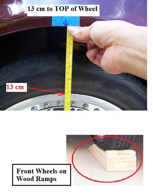
23. Now: Install Wheels, Remove jack stands, LOWER the car and drive it up on ramps. Then:
Torque:
- Thrust Arm Subframe 18-mm Nuts: 110 Nm***
- Control Arm Subframe 18-mm Nuts: 110 Nm***
NOTE: As a practice, tighten the Wheel Bolts to 110 Nm using a Torque Wrench so you have an idea of what 110 Nm feels like because under the car, it is virtually impossible to fit a torque wrench, so use your muscles and feel (I did!!!).
*** Torque these bolts ONLY with car on the ground and weighed properly
- 150 lb each front seats, 150 lb center rear seat, full gas tank
- I had my 16-year-old and 11-year old kids to sit in the front and that is good enough for me!
Also, after install, the car WILL appear higher than before, don’t panic yet!
Give the Bilstein struts 30 minutes to settle down before torquing these Thrust Arm and Control Arms Subframe 18-mm Nuts to 110 Nm.
NOTE:
- Old Bushings worn out:
- Car on Wood ramps when torquing the Thrust Arm and Control Arm nuts.
—————–
The Alignment DIY:
1998 BMW 528i (data from NTB Alignment Sheet):
- Toe-in: -2 minutes to + 6 minutes (or 2 minutes +/- 4 minutes) —> Adjustable
- Camber: -0.7 to 0.3 degrees (or -0.2 degrees +/- 0.5 degrees) —-> Unadjustable (unless you install a camber kit, off topic here!)
- Caster: 6.0 to 7.0 degrees (or 6.5 degrees +/- 0.5 degrees) —-> Unadjustable
—> Only Toe-in is adjustable for E39.
1. If you did not sleep through your High School Geometry Class, then I will share with you this best-kept secret: Alignment DIY.
- There are 60 minutes (‘) in one degree (A circle = 360 degrees); and 60 seconds (“) per minute.
- If you read Alignment Sheets, very often car mfg’s misuse these symbols (‘) and (“). For the most part, it is minutes not seconds.
- Review Tangent and Arctan. Basically, for each stock tire front to rear rubber part is 540 mm.
- Since toe-in is given as degrees and most of us don’t have the sophisticated alignment tool to measure degrees, I measure using the difference (in mm) in front and rear part of the same tire (front and rear measurements).
- Tangent (2/60 degrees) x 540 mm = 0.314 mm TOE-IN!
- Tangent (6/60 degrees) x 540 mm = 0.942 mm TOE-OUT!
2. Requirements:
- Car with full gas tank. I by-passed the weighing business (150 lbs front seats, 150 rear seat garbage).
- Tires at 35 psi. All 4 tires should be the same make.
- Level garage at spots where car parks. Take measurements using Carpenter Level.
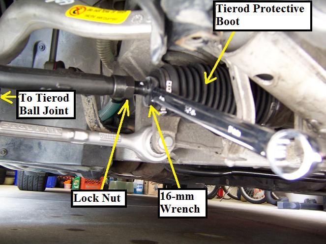
- 16-mm wrench for tierod adjusting bolt and adjustable wrench for lock nut.
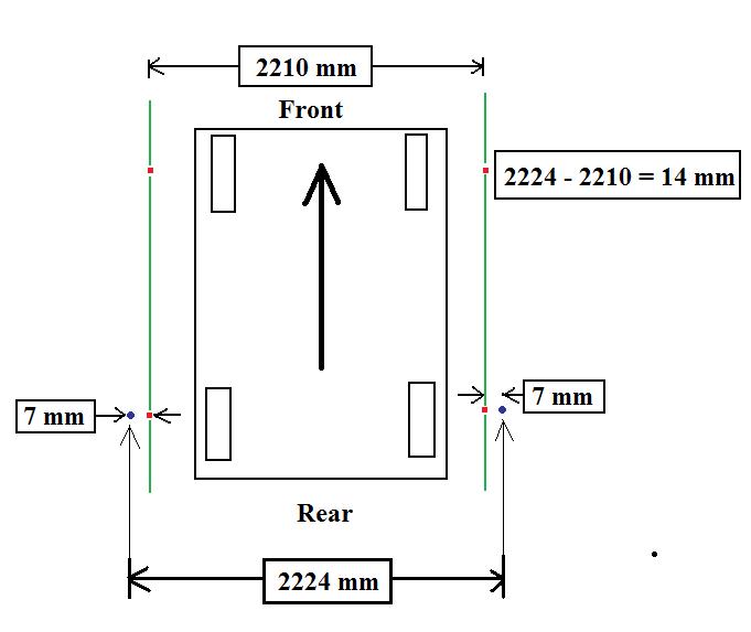
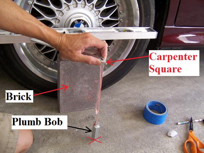
3. The whole idea is to establish parallelism. Using the carpenter square and level coupled with Plumb Bob (see pic), measure the track width at wheel (Front and Rear) Hub Centers.
Drive car straight out garage. Calculate the difference between Front and Rear Tracks.
Published Values are:
- Front Track Width = 1512 mm
- Rear Track Width = 1526 mm
- Difference is approx. 14 mm
4. Put car back to similar spot. Apply Parking brake and whatever you do, do NOT move the car after this step, otherwise, you will redo the whole thing again. Remove key and rock steering R and L to lock it. Make sure SW is dead center.
5. Now mark the Front and Rear track widths (with carpenter square) on masking tape on the floor. Since the Front track width on each side is 7 mm (14 mm/2) less than the Rear track width, add 7 mm lateral to the Front Mark.
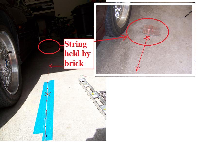
6. Using a string (held by brick) and draw a straight line between front and rear marks. This represents the straight axis of motion of the car. This line will be used a reference line:
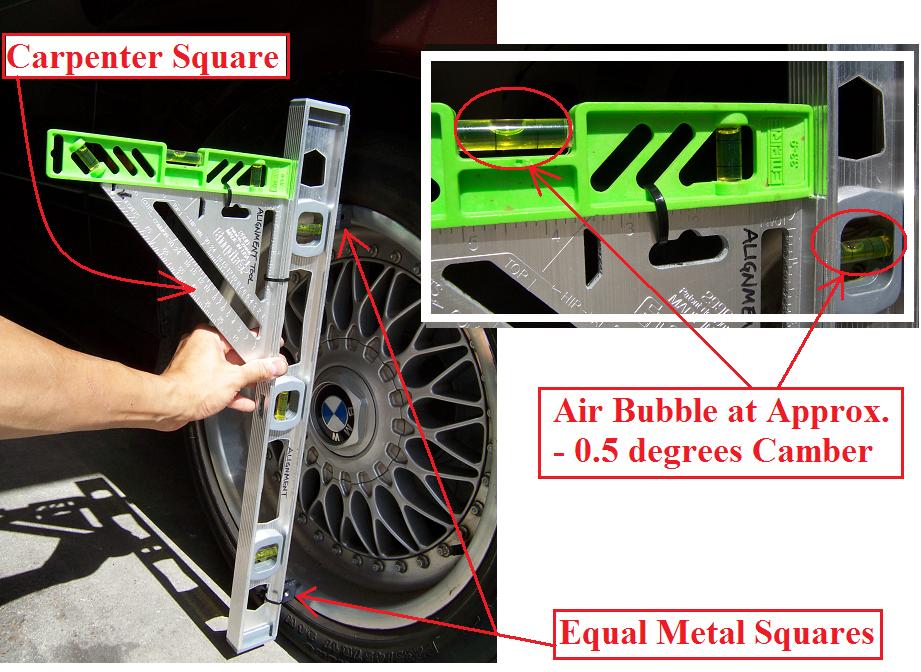
7. Now measure Camber. I have calibrated my device so when the bubble is barely out of the marks, it is roughly 0.50 degrees (or 30 minutes, which is half of a degree). In fact this is –0.50 degrees, so it was good:
8. Now measure the toe-in: -0.314 mm (TOE-IN) up to +0.942 mm (TOE-OUT). You can actually set it at zero. Some people set it at –1.0 mm, which is very typical of many cars.
A bit of TOE-IN is good because the crown of the typical road will have the tendency to bring the tires out a bit. Some people set TOE-OUT more than spec for aggressive track use:
9. Go for a test drive on a smooth highway.
- The chances are the SW is not dead center. Make a note.
- Let’s say car goes straight but the SW points a bit to the Right.
- Bring car back to driveway.
Now, when SW is turned dead straight, both wheels point a bit to Left.
Then adjust in equal increments (for example, pull L side in and push R side out equally). Again do this in equal increments.
One complete turn of the tie rod moves the Tie rod by 1 mm but mathematically it changes the tire difference readings by 2 mm.
- Use liquid paper to mark tie rod original reference position so you know how many turns you have done.
- Tighten the Lock Nut (do not over-tighten it) to lock the tie rod.
Go for test drive again and adjust the Steering Wheel position as appropriate.
Enjoy your Ultimate Driving Machine!!!
| BMW Part Number | Item Description | Price | QTY | Sub Total |
| VE3B406H1 | Bilstein HD Front Struts | $167.08 | 2 | $334.16 |
| 31336752735 | Strut Mount | $43.18 | 2 | $86.36 |
| 31331091868 | Rubber Boot for Strut* | $2.35 | 2 | $4.70 |
| 31331091867 | Spring Pad UPPER | $3.72 | 2 | $7.44 |
| 31331091864 | Spring Pad LOWER | $3.54 | 2 | $7.08 |
| 33326760374 | Self-locking collar nut M12X1,5-10 ZNS3 | $1.90 | 2 | $3.80 |
| 31351095661 | LEFT Swing Support | $35.61 | 1 | $35.61 |
| 31351095662 | RIGHT Swing Support | $35.61 | 1 | $35.61 |
| 31351093108 | Stabilizer rubber mounting | $20.00 | 2 | $40.00 |
| 31121141717 | Left tension strut (Thrust Arm) LEMFOERDER | $160.00 | 1 | $160.00 |
| 31121141718 | Right tension strut (Thrust Arm) LEMFOERDER | $160.00 | 1 | $160.00 |
| 31106769441 | Hex bolt with washer M12X1,5X120 | $2.96 | 2 | $2.96 |
| 33326760668 | Self-locking collar nut M12X1,5-10 ZNS3 | $.62 | 4 | $2.48 |
| 31121094233 | Left Wishbone (Control Arm) LEMFOERDER | $133.14 | 1 | $133.14 |
| 31121094234 | Right Wishbone (Control Arm) LEMFOERDER | $133.28 | 1 | $133.28 |
| 31306779823 | Collar screw M12X1,5X95-10.9 | $2.33 | 4 | $9.32 |
| 32111094673 | Tie rod Left LEMFOERDER | $60.78 | 1 | $60.78 |
| 32111094674 | Tie rod Right LEMFOERDER | $59.14 | 1 | $59.14 |
| 32131092876 | Rubber boot For Tie rods | $7.29 | 2 | $14.58 |
| 32111137132 | "Oetiker" Clamp | $1.79 | 2 | $3.58 |
| 32131094100 | "Oetiker" Clamp | $2.30 | 2 | $4.60 |
| 31221093427 | Front Wheel Bearing (mfg = F-A-G)** | $125.42 | 2 | $250.84 |
| 31121093843 | Wheel Bearing Bolts | $2.25 | 8 | $18.00 |
| Total | $1510.00 (approx) |
NOTES:
The issue of re-using nuts/bolts: I use new nuts/bolts, but most BMW mechanics re-use the bolts, they simply change the nuts. If you go this way, note that the New Lemforder Items (tie rods, Thrust and Control Arms) come with the extra nut in addition to the Ball Joint Nut! So the only thing you may need are the Pinch Bolts Nuts holding the strut in to steering knuckle: PN 33326760374.
Control Arm Bolt same is the same PN as the Pinch Bolts for Steering Kuckle)